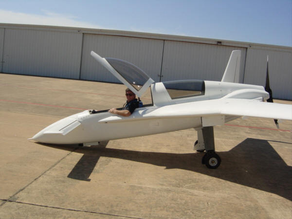
Air Vent Fix: OK...now that the very initial flights have proven the thing can fly, it's now time to make it inhabitable! You see, after Dave flew her a little higher, a little faster and a little longer, a few shortcomings were detected. We had fixed the brakes the previous day, and the flights were safe and all...but a VERY important item was not functioning at all - the pilot air vent! I had consulted with several Long-EZ builder/flyers here in Texas as to an air vent location that was not on the front canopy. Several Longs in the area use a pitot-like slot on the leading edge of the strake with great success. So, that is where I installed mine...except...this is no Long-EZ. For whatever aerodynamic reasons, the strake location for this vent is in a dead pressure zone and absolutely NO AIR is forced into the cockpit! Dave said you could light a match in front of the vent! And, as it was a very sunny 96 degrees, high humidity, Texas day and those canopies basically making a solar cooker out of the cabin...we HAD to do something...anything...to get air in there!
While I was thinking about how to make a scoop out of 5-minute epoxy as we had no spare time to waste, Dave was digging in the trash can. (yep, you read that right) He pulls out a Dr. Pepper can and starts cutting it down. Scott Carter happened to have some Duct tape in his bird and this is the fix we cobbled together. All we needed was to scoop a little air in from outside the boundary layer, and that is exactly what the scoop did. You will see it
on all the flight photos from the next few days - in fact, it saved the weekend of flight testing! It actually held on there for several flights until the sun had heated the tape up a few times and it began to get less sticky. Not wanting it to go through the prop, but not wanting to spend the time moving the vent...I took an afternoon and made a semi-permanent scoop.
I simply took a piece of blue foam and cut and contoured it to small scoop shape. I then put packing tape on the fuselage and strake area as mold release and tapped the foam shape to the vent area and applied 2-ply BID with fast West epoxy over the whole thing. A few hours later, I popped the new scoop off, trimmed it up, reattached it with RTV silicone, and shot it with a little white primer to match. Ta-da! Now, I have PLENTY of air...and drag along with it. Yeah, I know...I know...
I will get rid of the scoop and put in the NACA vent in the canopy someday. Right now, I'm concentrating on flight testing and flying off those 40 hours so we can make Rough River! At least I can now do it without melting!
UPDATE 1-31-06: After flying with the "temp" vent for more than a year now, I figured it was time for a change. I REALLY like the eye-ball vent right where it is on the left side of the cabin...so, I wanted to try "one-more-vent-idea" before committing to the NACA scoop on the canopy. This will be quick and dirty trial at first, as I have to repair the original hole in the same area...it won't be that big a deal to make two fill-ins if this doesn't work. I started by removing the temporary scoop and taping off the original vent hole. Then I drew out the basic shape of the forward vent. I want to keep the original "lines" of the strake/fuselage intersection
so from a distance, the vent won't be so noticeable (in theory). Next I just cut away and removed the material to create a rough vent shape and then routed out more material to create a inward ramp depression. From the front, the vent hole looks like this. Again, it LOOKS like it will work. ;-) From the inside, the hole does not seem very big at all. Remember, this is just a rough test...I'll fly it, see what kind of flow I get and go from there. I might scrap this idea completely...but I have to "experiment" first, right!?!
UPDATE 2-2-06: I flew yesterday to test the new vent location and I'm happy to report that air actually flows through the hole this time! Actually much more air than the temporary scoop ever did, which will come in handy in the hot Texas summers. So, now that I have proven that the location is good, it's time to make things a little more permanent. I chucked up a rasp in the air-drill and removed the rest of the fuselage core foam and shaped the rest of the intake ramp. Then I mixed up a batch of "flocro" (flox and micro balloons) and smoothly filled and shaped the ramp area, then covered it with 2-ply of BID glass. I did the same thing to plug the old vent hole.
Overall, the new vent keeps the original shape of the strake taper and I'm hoping that when it's finished it will not detract from the "lines" of the aircraft. If it does, I'll just "pookie" it all back in and start over. No biggie with a composite airframe still in primer. ;-) Tomorrow, I'll apply the external filler and take it to final shape and cover with primer.
UPDATE 2-6-06: Holy smokes! That vent works...and works way too well. Between the rough draft and the final product the ramp depth and the size of the hole got much bigger. I guess I got a little carried away on the foam removal. When I flew it, I couldn't turn it off - when I tried, it made a horrible loud buzzing noise and the eyeball vent would move around like it was possessed. OK, too much air now. (sigh) So, I got the "speed tape" out and filled up the ramp to reduce the inlet size. I flew it again, and it had just the right amount of airflow - which was still more than the original vent
could produce. With the new dimensions in mind, I put back some of the foam I had taken away, filled the ramp in with light weight filler and went back to work shaping and smoothing the inlet ramp and sides. As you can see, the inlet hole is much smaller than before. Confident this version will work, I added one more thing I wanted to test - a bug screen RTV'ed to the inlet. This metal mesh will certainly keep the mud-daubers and wasps out, but I'm not sure how it will hold up against 250mph airflow...we'll see. Now, the
version 4 final product looks pretty good and has an inlet with a more reasonable inner diameter. Once the primer and RTV dries and I get some time, I'll flight test it again and let you all know how it goes.
UPDATE 2-26-06: It works just fine and the screen didn't even come loose at full cruise. I'll fly this vent for awhile and see how it holds up, but looks good so far.
Status: Version 4 - Complete
Noisy Cabin Fix: Something else that was noticed on that #2 faster flight - a screaming tone in the cabin at about 160+kts. We all looked around the nose area for something that could make a noise like that - it ended up being the thin edge of the canard fairing cover. Normally, this area is built up into a glare shield the hangs over the instrument panel. Because this was purely cosmetic in nature, and I knew we would have the canard on and off several times over the testing period, I left it off. With the canopy closed, air was being forced under the lip and making that this edge act like a "reed" in a woodwind musical instrument. So, the simple fix was to add a thin slice of Confor foam and Duct tape to the lip to act as a seal. It worked perfectly on the next flight...and thus it too will remain through the rest of flight testing.
UPDATE 12-31-04: Well, I finally got around to finishing the canopy seals and sound proofing for the cabin. The biggest improvement was achieved by making that foam plug for the aft turtle deck - significantly reducing the engine noise. Now to get rid of some of that 250+ MPH wind noise. The Berkut longerons have drip rail molded into them for both catching and channel any water that might slip past the lips and to accept P-strip insulation. So, all I had to do is attach some P-strip weather stripping to the bottom of the canopy rails and bingo! I also put some around the canopy loops to finish the perimeter seal. The front edge of the front canopy didn't have enough room for P-strip, so I just used a little
strip of foam insulation and it fit just fine. Needless to say, this cut down the cabin noise quite a bit but I still have some whistling up front that I need to chase down. Well, at least I'm getting closer.
UPDATE 8-31-05: The harmonic was found to be caused by the aft compartment cover. It was basically vibrating in a harmonic range like a drum head. I first used some lead shot in a baggie to dampen the vibration. This worked, but after I installed the aft camera mount point, it did the same thing. Problem solved...moving on.
Status: Fixed/Complete
Left Outer Gear Door Fix: Faster speeds yet revealed that the left gear door was being slightly pulled open by the force of the slipstream airflow around 200+mph. (that's tornado-like forces, ya know) The fix was very simple - I needed to "warp" the gear door slightly so that the front edge would close first, and the force applied by the "warp" would more firmly hold the door closed. So, I made up a quick and dirty torture jig and heated the door up with the heat-gun. After it cooled, it was now warped about 3/16"...exactly what I was shooting for! It too worked perfectly on the
next test flight!
Status: Fixed/Complete
Wing Attach Bolt Covers: While I had some time doing other things, I installed my wing bolt covers. I had cut them into tear-drop shapes from .020 aluminum sheet, primed, and painted them white. They simply stick onto the wing with RTV silicone. They work fine, but the only problem is that I had to remove a wing the next day! (sigh) Oh well...I'll re-install them later.
Status: Fixed/Complete
Heat Shield Damage Repair/Cowl Fairing Clearance: After a few flights, I noticed that the left upper exhaust pipe was rubbing up against the upper cowl's heat shield. The shields are good for 2000-degrees of radiant heat, but direct contact to 1400-degree pipes was not in the plan. They clear when the engine is now running, so I figure it was the engine's torque that was moving it up a little. So, after we had re-adjusted the exhaust pipes down lower, I replaced the singed heat shield with a fresh one. Ah...that's better.
UPDATE 9-15-04: OK...well...I fixed the symptom, but not the problem. Even though the pipes were lowered on the aft end, the forward end of the pipe was still a little too high and during high-torque loads was still contacting the upper cowl. The contact would abrade the heat shield and let the radiant heat through to the upper cowl. After a few hours of exposure, the exterior of the cowl was showing signs of heat damage and began to blister and peel. So, a more invasive solution was in order...and since it was raining cats and dogs, nature provided me a good excuse to go into maintenance mode! I brought the cowl home and cut off the top of the exhaust fairing. Then bonded a new 3-ply BID carbon arch in place, using the existing edges of the original fairing as a guide. As you can see here, the fairing now extends further
forward and is also 1/2" taller that the original. After semi-cure, I lathered the outside with micro and re-installed the heat shield material. A little sanding and primer, and we are back in business the next afternoon. A few engine run-ups proved that everything now cleared the cowls with plenty of room to spare. Now...it's fixed!
Status: Fixed/Complete
Additional Cooling for Cylinders 3 & 4: Now that I'm getting closer to the maximum cruising speed for this airframe, the engine is having to work harder to push it through the air - obviously this generated more heat. The good news is that all the temps are in the normal operating ranges for all power settings - 290-370 degrees with oil temps from 170 to 190 degrees. It's not even really a "problem", but the two cylinders that are the closest to the firewall run about 40 degrees hotter than the ones further aft. The ideal situation would be that all 4 are cooled equally, but it is rather hard to get air to make a turn up and
into the front cylinders. This is a very common issue when using the arm-pit cooling scoops as the air wants to just rush in and continue straight back...skipping the first two cylinders. Actually, the engine would be just fine as is...but you know me...gotta at least shoot for perfection. So, I cut out a couple of flow guides from .050 aluminum. Instead of making a ramp to deflect the air up into the front cylinders, these guides help guide the air to the cylinders from above. Attachment is simple, but due to a carbon fiber cowl, an insulating ply of glass BID was also required. The two flow guides are attached to the cowl with flox, flox rivets, and 2-plys of BID. As you can see from behind, they just curve upward toward the cylinders.
Results thus far have been inconclusive...one flight they run cooler, the next they run hotter. I'll leave them in for now and continue testing.
UPDATE 9-19-05: I'll be making a whole new section out of what I uncovered here - a BIG can of worms. In short, I've solved the cooling issues...but it took several itterations to get it right. More to come...
Status: Fixed/Complete
Rudders Un-porting at High Speed: On one of my test flights at 215kts true, I started getting a low frequency "shimmy" in the back end of the airplane. It was kinda like a very out of balance tire at moderated speed...except only in yaw. Needless to say, this was rather alarming to me having never experienced this before...and on a flutter test run to boot! I quickly decelerated and the shimmy went away. After a short conversation with Dave, it was determined that the rudders were un-porting (flapping in and out) at high speeds as they are trying to couple to the inside or outside winglet slipstream. There are two possible fixes for this common issue - stiffer rudder return springs, or the use of "gurney" flaps. Since I didn't want to change the rudder feel at lower speeds, the best
fix was to go with the gurney flaps....as they are relatively low drag and are more effective as speed increases. For those wondering, a "Gurney flap" is a small buildup of material that is added to the trailing edge of a control surface that causes the slipstream of air to "trip" over it. As it trips, it applies a small force to the control surface...in this case, pushing it back into neutral position. The material used can be just about anything - I used some 18-guage wire I had left over. I started with the wire running the full span of both rudders held on with white plastic electrical tape. A single test flight confirmed that the full span gurney flaps were both effective...and WAY TOO BIG! Through several test flights, I kept trimming the
flaps down in size to what I have on there today - 6" long on the left (heavier rudder spring), and 8" on the right (lighter rudder spring). This combination is working well so far, but I may continue to experiment and get them down to the minimum required. After all, that is what this is all about!
Status: Fixed/Complete
Left Roll & Yawing Tendency: With each flight, I am becoming more and more "tuned in" with the airframe. I am now starting to notice subtle things that have been masked thus far by the mind and body numbing effects of adrenaline. Two such items were the need for continuous right rudder pressure and a left rolling tendency at high speed. I had just been centering the ball instinctively, but now I had reached the point that I actually noticed I was doing it. So another simple fix was needed - a rudder stop. I used a 1" phenolic block bonded to the winglet side and a piece of ply wood bonded to the rudder side. This way, I made the ply wood block over-size so I could sand it down to the final length. It took about 3 flights to adjust it down and get it right...but now she flies ball centered.
The left rolling tendency was lessened, but still present. The weather that day was not conducive to test flights, so I bit the bullet and pulled the cowls off. I checked for leaks and abnormalities and found none. But while the cowls were off, I figured it would be a good time to shim the right wing and lower the incidence (thus helping to counter the left roll). I used a single thin washer and sanded off the cad plating to make it even thinner. The net result was about a 3/32" drop in the leading edge...a very minor correction. A few flight tests later, and this has improved the left roll, but it is still there. It also threw off the rudder fix, as the winglet incidence was also affected. (ugh) With canard airplanes, the roll and yaw functions of the wing/winglet are coupled...
change one and you change both. It took some time, but I finally got it all trimmed out - she now flies centered, in trim, with ball centered...hands and feet free!
UPDATE 8-31-05: During the first annual (see below), I took the wing and rudder shims out and started over. Knowing more about the flight characteristics of the plane, I was able to better understand what was going on. I know have ALL the shims removed, and the roll trim springs set correctly. I do have to use roll trim at higher speeds, but I can damp the roll with trim at ALL speeds.
Status: Fixed/Complete
Increasing Aileron Trim Effectiveness: With only 1.2" of total travel in the Ray Allen trim servo, spring pressures are the key to making it effective. I have effective aileron trim up to about 165kts indicated...above that, I run out of travel. Right now, I'm waiting on new springs to arrive from Century Springs. Not much I can do here until they arrive....
UPDATE 9-23-04: As you will read below, I was finally able to fly again today. I replaced the right side trim spring with a fresh, longer one - as it was before I trimmed it. I did not do any high speed runs as I was just orbiting the airport (at 180kts indicated, 197kts true), but the initial data points to having FULL TRIM AUTHORITY. Yeah! Later, I got her up to max cruise speeds in the 220 to 225 TAS range that weekend...all well within trim range!
Status: Fixed/Complete
Engine - Rough Idle/Stumbling/No Low Idle: (Long winded, but the detail might help someone else someday) Well, the good news is that I have learned more about the mechanical fuel injection system in 2 days than I ever learned about carburetors with my modified 1970 Ford Mustang street rod (it had three of them all linked together). The bad news - the plane is grounded until I make some changes. OK...here is the story: The engine has been performing well to this point...BUT...it has always been set at a high idle (900+RPM) and was really set too rich (always black soot on the prop). So, a few days ago, I adjusted the idle to a lower setting (800RPM) - that was still higher than normal (600-700RPM) but I didn't want to change it too much and the engine didn't want to run any lower anyway. So, I blasted off and completed a great 2-hour test flight...even had a little 4G fun with some small puffy clouds. Now, on landing I was a little high on short final so I pulled the power WAY back and kept it there. I easily made the runway, but as the mains touched down the Bus Voltage alarms and lights were going off and my roll out was very abbreviated. You guessed it...the "big fan in the back" was no longer turning! I coasted off the runway and easily re-started the engine...I guessed that I took the idle too far down...but really this should not be happening at the 800RPM range. Just as I was fiddling with the idle, a fellow EAA'er and A&P dropped by to check in (great timing Tom!). After some investigation, we found the idle mixture was way too rich and adjusted it. Idle was much smoother (no soot either), but still not down where it needs to be - it just would not sustain idle at less than 800RPM. (Grrr!) The next day, a new problem showed up - stumbling/hick-ups. The engine would purr along smoothly at 850RPM for several seconds, then it would "stumble"...drop a little RPM...shutter (choke)...become silent for a split second (as if turned off completely)....and then return itself to a smooth high idle...and repeat. OK, weird!! It did it the same on either mag or ignition or both, either fuel tank, boost pump on or off, lean or rich, and did it consistently over and over every several seconds at 850-1300RPM. The only thing that varied was the severity and duration of these "stumbles" mainly dependent on RPM at the time (less the higher the RPM). Also note that the EGTs are constant, as was the fuel pressure (as measured into the Bendix servo).
Tom and I were baffled...which is a normal trait for me in this area...but NOT for Tom! We checked for all the standard stuff too: contaminated fuel - NONE, checked and pulled the injectors - CLEAN AND CLEAR, checked for leaks - NONE...then Tom (the A&P) asked where the fuel flow divider was. "Don't have one", I responded. I explained that my setup from Aero-Sport Power didn't come with one, and it used only a small fuel distribution block between the servo and the injectors. This explanation was greeted with a "that's very odd" look! To explain, a "flow divider" is an active device that is commonly referred to as a "fuel spider" - cuz it kinda looks like a spider once the lines are connected. It is installed in-between the Bendix fuel metering servo, and the 4 injector nozzles. It's purpose is to evenly distribute the fuel to each of the four injectors, but it ALSO has a small diaphragm and variable spring valve inside that restricts the fuel flow and regulates injector feed pressures at low RPM, and allows open flow at higher RPMs. A fuel "distribution block" is just that...it takes the feed fuel from the servo and sends it to the 4 injectors directly without and additional pressure or flow regulation. Starting to make sense now?
Long and short of it...now, I had something to look into! The next morning, I called Airflow Performance first for some professional help, as they had reversed my mixture mechanism on this unit awhile back. I spoke with Kyle for at least 30mins going over what I had experienced. He was a wealth of information and troubleshooting advice, he was stumped too until I happen to mention the lack of flow divider - BINGO! Immediately, the conversation changed and focused on that as the most plausible cause. My next call was to Aero-Sport Power, the folks who built and tested my engine setup. Bart and Sue were very accommodating! Bart explained that "typically" with up-flow setups (servo to injectors is all up-hill) a flow divider is not always required. The weight of the fuel in the lines and gravity help regulate the small pressures
and even Lycoming ships helicopter engines without flow dividers...just distribution blocks. However, Bart said he would immediately send me (for Saturday delivery, no less) a Bendix flow divider, some stock for making a bracket, and an assortment of fittings to make running the lines easier. Great folks there at ASP!! No questions, no games...just pure help! No one could really anticipate this problem, and the engine does run just fine at higher speed...so...this should fix things right up. Only problem...it's going to take some time to install it as there is little room to work with, and test it.....this all puts making Rough River in doubt. Oh well, if that is what it takes to be safe, that's what's going to happen!
I'll update this section as make progress. Meanwhile, the new transponder just came in, so I guess I'll be installing that and fixing a few other things while I'm down for maintenance....again.
UPDATE 9-20-04: A little progress... I fabricated a bracket and mounted the fuel divider and hooked up two of the injector lines. The bad news - the other two injector lines are too short and have to be replaced. I had to mount the divider off to the side as there was not enough room where the block was - making the left side runs too short. Aero-Sport Power is shipping new ones as we speak. So, I'm working on finishing the rear seat shoulder hard points and "hell hole" area.
UPDATE 9-22-04: And a little set-back... Aero-Sport Power was nice enough to over-night a couple of new fuel injector lines to I could install them. The IRONIC set back is that the FedEx flight out of Canada was scrubbed by A FUEL LEAK! (sigh) So, I lost another badly needed day! The lines did show up the following day and I was able to get some engine work done. The injector lines were easy to install and went quickly. I also finished the mounting bracket for the fuel spider. Now the HARD part - putting it all back together! Now that the fuel divider is taking up space in the area, my access to the oil cooler mounting bolts is cut off. Uh-oh...I don't even know if this system is even possible now! (Crikes! Now what?) Well...I re-design the re-assembly sequence and see if I can make some room, that's what. OK...this was a frustrating experience...make a mental picture of this: It's dark now, so my only
light is a drop light in the area, I have tools all over the floor under the engine and a big fan is blowing on me since it's about 90 degrees. I wrestled with the oil cooler and bolt for at least an hour and determine I have no choice but to dis-connect the oil line to make room. (I have only two hands, and no help...) Now, I expected some oil to come out - but not a quart of it! I loosened the line with one hand, and held the cooler assembly with the other. Oil began running out immediately...but since the fan was blowing, it was dropping at a 45-degree angle...onto the tools. I grabed some shop towels, wraped the oil line with them and duct tape...that only slowed the flow. I had to let go of the cooler and it swung down and it TOO starting pouring oil....ACK!! Now, in my haste to stop the oil...I bumped the drop light, it fell and broke! So, now I'm in a rain storm and flood of oil, in the dark and at my personal frustration peak! Such is work on airplanes....
OK, ok...a short few hours later, I got the oil under control, the cooler back in place...and believe it or not, I got all the nuts, bolts and washers in the right place - in the dark, no less! So, it's a very tight fit but everything fits without rubbing and I now know how to put it all together again. I'm glad that's over...now, I hope it actually fixes the problems!
UPDATE 9-23-04: SUCCESS!!! Today, I rolled the plane out, borrowed a few EAA'ers to act as fire-crew and fired the engine up. She ran more like a Swiss watch rather than a Lycoming engine - very SMOOTH and even idled without hesitation. Man, did THAT fix make all the difference in the world. I can idle smoothly at 700-750 now - no surging, no stumbling, and smooth as silk. So...I jumped out, danced a jig, put the cowl back on, buckled up the parachute and taxied out for take-off. I noticed I could taxi slower now at smooth idle and there was no stumbling when I ran over bumps, etc. Static RPM was higher on T.O. roll (a little more power now available), and the climb rate was about the same. I circled the airport at 3500ft (there is only 1000ft between Class D TKI and Class B DFW airspace to work in) for about .5 hours until sunset forced me back down. It was a great day! This fix cost me a week and a half to resolve, and I may miss Rough River because of it. But, I have a
better running and safer plane to show for it. Some may say it was an "unnecessary grounding"...but I say, "there is NO SUCH THING" when you have a known problem. I sincerely hope this problem documentation can help someone else avoid, or diagnose quicker, similar issues. Good luck and Godspeed!
UPDATE 11-14-04: I had the opportunity to inspect everything under the cowl during the installation of the spinner. After some 15+ flight hours, the small 'S' shaped aluminum bracket ( seen here) had cracked through at one of the bends. The thin brittle aluminum used was no match for the vibrating mass of the spider. So, I took this opportunity to replace it with a thicker steel bracket with less of a bend in it. That will hold it.
Status: Fixed/Complete
Front Wheel Replacement: Ok, under heavy recommendations from the local Long-EZ drivers, I frinally got around to replacing the front nose wheel. The Berkut hardware kit came with a Ken Brock nose wheel and although it might have worked without incident for years, there have been reports of break-ups over the years - mainly with the heavier canards. I bought a Gerdes wheel several months ago, so I put on the extra bald tire I had laying around and put it on the plane - it took about 10 minutes. Well...this mod could have been for nothing at all, but I did have the parts and it did provide a little peace of mind.
Status: Fixed/Complete
In-flight Scare #3: I just had my first gear extension failure last weekend (10-30-04) - the low pressure switch failed. The pump ran in the up mode, but would not budge on the down select. So, I used the dump valve and reduced the line pressure to zero...still no pump. I aborted landing and circled while I tried to get the gear to cycle. Still up..no down. After several tries, I figured I'd have to fully dump the gear and fly off the fuel and try a light landing with only the pogo stick holding things overcenter. Fortunately, just as the gear reached the fully extended mark the pump fired up, I closed the bleed valve and the gear fully locked over-center. I landed with no problems but recieved several jabs and "limping airplane" comments from fellow EAA'ers - all in good fun since everything turned out OK. I put the plane up on stands, and it repeated the problem on the ground too - confirming it was the VEP low pressure switch. So I "borrowed" a different brand of pressure switch off my hangar mate's plane and got things working again but the new switch was much more sensitive to the restricted gear door lines I had originally installed (1/8" Stainless Steel with too small ID just like the brakes). So I spent the next Saturday ripping out the old tubing and re-installing the new, larger ID tube. Man, that made all the difference in the world!!! The gear has never operated so smoothly! I should have done that months ago. Anyway, for the record I had originally installed VEP pressure switches...I consider them "crap" compared with the Suco or Whittman switches that Dave now recommends. I have two new Suco's on order...to replace the ones I "borrowed". (Thanks, Scott) Here is what the temporary assembly looks like with the Suco switch in the back ground and the VEP high pressure switch still in use...for now!
Status: Fixed/Complete
Hydraulic problem #2: (Updated 12-8-04) My hydraulic system has never been 100% from the beginning - there has always been a small leak internal to the system itself. No fluid is leaking OUT of anything, but it IS bleeding pressure and not holding a constant level. This means that the leak is either the piston seals in the actuators, the dump valve, or in the pump itself. What are the symptoms? Well, in normal operation, when you move the gear switch, it turns the pump on and extends the main cylinders to retract the gear. When they reach maximum extension, the pressure in the system builds up until the pressure switch activates (becomes open circuit) and turns the pump off. It should stay off for a considerable time as the pressure should remain the same until the pump is reversed to let the gear back down in opposite fashion. The problem is that either extended or retracted, the pressure bleeds down in a matter of seconds to minutes, causing the pressure switches to re-activate the pump for a split second to re-pressurize the system...a few minutes later, it happens again...and again. During first flights, and up to just a few days ago, this was happening in the order of 2-10 minute increments...annoying, but flyable. A few days ago, the high pressure "gear-up" side was OK, but the low pressure "gear-down" side was continuing to cycle every half-second! Totally unacceptable...and hence the new problem. I'm starting to understand the retractable gear counter points of "not being worth the trouble". ;-)
To diagnose this one, I started by capping off the outboard gear doors as they would be the easiest to fix...no joy. So, I focused (prematurely) on the main hydraulic cylinders. I took the Airight cylinders apart, and looked at the O-rings and seals very carefully. I noticed that the machined groove in the piston is twice as large as the O-ring and Nylon scrapers. This allows the O-ring to float and possibly even become diagonal in the groove. I don't even know if this is as it should be...but I did remove the O-ring and compared it to a new one. The original was a full .030" smaller - it had shrunk or had been slighty worn away...so I replaced them both. This had an immediate effect of reducing the "half-second" cycle times to more like they were - 2-7 minutes apart. I hooked the gear doors back up, bled the system and kept cycling the gear for about 30-mins. Some buddies had dropped by and were looking things over and while they were there...no problems...the MINUTE they left, however, the "half-second" cycles WERE BACK! Dang it! I guess she was just showing off in front of company.
The next day, I went back out to the hangar and blocked off all the cylinders and tested only the pump and dump valve. Much to my dismay, I ran the pump in BOTH directions and it just kept cycling about 4-5 times a second!!! Definitely something wrong here! It was only slightly slower with the cycles on the low side, faster on the high side...figures with the differences in pressure. Just to be sure, I then blanked off the pump itself with only the pressure switches hooked in - SAME effect. So...bad pump...now what? I took the pump home, took it apart to see if I could find anything that was blatantly out of order.
For all you Berkut, Glasair and marine users of this pump, I'll describe in text and pictures what I found since there is virtually NO INFORMATION on the Internet regarding this pump. This marine application website (look at the Pump/Motor bottom reservoir Design I section) was the most helpful, but it does not show or list anything concerning the valves - figures, huh. Oh, well...with wrenches in hand, I began tearing it down. The pump consists of three main parts - the motor, the pump/valve deck, and the reservoir. One screw with an O-ring removes the reservoir from the pump body, exposing valve assembles and intakes (as labeled in the picture). Two more screws hold the 12v motor onto the top of the pump/valve body. Next off was the Nylon fitting for the dump valve return line. The return conduit in the pump also had a spring and ball valve - I can only guess that it was the valve that facilitates the return system fluid back-pressure into the reservoir. Originally, this pump had a plug in this hole that I replaced with a fitting to now serve a dual purpose. The two outboard (dark) spring valve assemblies are the thermal expansion valves. Those are relief valves that only activate if fluid is trapped in a non-operating pump and expands due to excessive heating. Both of these valves have never been activated on my pump since they are still packed with assembly grease. I didn't get a picture of them, but the two (shiny) valve assemblies in the center are the High and Low pressure relief valves and have the same spring/ball setup as the thermal valves with one exception - they are setup to have adjustable pressure. The whole assembly can be screwed in or out to regulate the amount of spring pressure exerted on the ball valve - the higher the spring pressure, the higher the fluid pressure needed to release the valve. I also took the valves out of the side caps - these were not ball valves, they look like large needle valves. One of them did have a small gouge in it but at the base, not on the ramp of the "needle" portion. They look like the were machined with a groove that looks like it was for an O-ring but none was found. The assembly looks like this. The valve seat is just a flat opening with a hole in the center. With it all taken apart, here is parts spread. Well, I didn't find anything blaringly wrong with the ball seats. Only interesting thing was the LOW pressure valve had a larger ball and larger hole in the seat - dunno why, but I bet it has to do with volume instead of pressure. Anyway, I took a sharp drill bit and lightly turned it on each seat to smooth the roughness out. It looks like the seats were powder coated (or painted) just like the rest of the pump block and were a little rough.
(Update) I've been asked by some loyal readers to give a little more information on my specific pump...so here goes: It's the Parker-Oildyne #637625 with an ordering code of 108AM19-CLBSP-1VT and was manufactured in 1995. The newer order code is: 108AM19-CLB-1VT. The "CLB" portion is CRITICAL for our useage! You can get the options break-out of that number, wiring diagrams, and flow circuits in a .pdf brochure directly at the Parker-Oildyne site. Or if that link doesn't work, I have a 2007 copy right here.
I also noticed, that during disassembly, the spring/ball shafts (the two center shiny ones) were tight but backed out much more than they are capable of being screwed in. It could have been that the relief valves were kicking in right about the same time as the pressure switches - set way too low. So, in theory, if I clamp those puppies down more, both sides will generate more pressure and the switches would really be the only "limiting" function and the valves would simply be there to save the pump from over-pressure should something gets stuck closed. OK...so my next plan of action is to do just that, re-install the pump, and see if it holds pressure. Then un-cap system components a section at a time and see if I can get the damn thing to work right.
UPDATE 12-9-04: Well, I re-installed the pump, primed it, and ran it with the dump valve open for several seconds to get all the air out that might be in the lines - both directions. Moment of truth...I closed the dump valve and the pump came to a stop. Good sign! I let it sit there for a little bit...and it cycled. DANG IT! I tried the UP (high pressure) side next...same thing...after a few minutes it cycled, but a with a shorter interval. Double DANG IT!!
So, here is what I have concluded. The original settings for the pump's HIGH and LOW pressure valves were indeed too low and too close to that of the switches. I can now adjust the HIGH and LOW pressure switches up without the pump running continuously or screeching. So, the "fast cycle" problem is solved and I have more flexibility with the switch settings. The pump also solidly stops at the switch limits...it now seems like it was "softer" before by comparison. Perhaps the valve settings were just at the 'open' hysteresis point of the switches...and causing the inconsistancies - further affected by the viscosity changes when the temperature dropped. However, I am right back where I started...a slow internal leak causing a pump re-cycle every few minutes.
Tomorrow, I call Oildyne to get the stupid thing rebuilt, or a valve kit, or something! Sad part is, I'm likely grounded for the rest of the year...with an absolutely beautiful weekend only a day away. (sigh)
UPDATE 12-11-04: Thanks to my hangarmate Scott Charlton's (Berkut#24) loan of his pump, I was able to quickly install it in my plane to get it flying again! His pump seems to hold pressure MUCH better than mine, but it too still bleeds down in the order of 5-10 mins even capped off from the rest of the system. So, this tells me that "something" is at least "more wrong" with my pump and he might have a similar problem. Both pumps are 1995-1996 vintage and sat around for years before use. The Oildyne guys were very helpful and I learned how the pump's guts work, and was also provided with an expanded drawing, proper system bleeding instructions and adjusting & cleaning instructions. We seem to think that the "poppet's" seals hardened (while sitting all those years) and are not fully holding the line pressures. They sent me a couple of new ones to try out...if those don't work...back to the factory it goes to be re-built. Meanwhile, I can still FLY!!!
UPDATE 1-5-05: I forgot to mention that I have recieved the new poppet valves from Oildyne. I have installed them into my pump, but have not re-installed the pump into the Berkut. Oh, well...no rush, I guess.
UPDATE 2-1-05: OK, while the plane was up on jacks for the next problem fix, I took the opportunity to put my pump (with the new poppets installed) back in the plane. The long and short of it is - it works better than Scott's un-modified pump, but it still cycles every once in awhile...but very much flyable! So, I'll fly with this one and we will likely send Scott's back to Oildyne to be checked out. I'll add some more here when we know what Oildyne has to say.
UPDATE 12-18-05: Since last writing here, I re-installed my pump (with the new poppets) in the Berkut - that's what I've been flying with for months now. It worked about as well as Scott's pump...still bleeding pressure every few minutes. Today, I performed a retrofit that I wanted to do a annual time but Scott's plane was still up on the only stands I have. Having just completed Scott's gear system, I wanted to finish up my pressure switch retrofit. I still had one VEP switch, and they both were still on aluminum tube "stalks" which were less than sturdy. The work was simple - first I removed the tube stalks and replaced them with direct coupler AN fittings - for a much more robust mounting. I replaced the old VEP switch with a SUCO and reinstalled both switches on the pump lines and also re-made the wiring. After bleeding the system and re-adjusting the pressure settings, my old problem of pressure bleed-down was again more bothersome. The SUCO switch is more sensitive to the pressure bleed as it has a higher amount of hysteresis - meaning it tends to flutter when the pressure is right at the break-over point. I NEED to get a resolution to the internal pump pressure leak. I'm calling Oildyne tomorrow!
UPDATE Spring of 2006: I was just reading this section again the other day and realized I had not made the final update. After trying the new valves, and pressure switches I was still having problems. I don’t know where it was, but I saw a picture of one of the "new" pumps that were being sold currently. I noticed it had a completely different pump section than what I have. Is stead of being rough cast and black, it was raw aluminum and look like it was much more machined than mine. Come to find out, Oildyne changed it's production methods sometime after my pump was made...the new ones have much better valve seats and tighter tolerances. Bingo! There's the likely problem. I contacted Oildyne about it all, and they suggested buying a new pump section. I contacted a local dealer and found out that the new pump section cost as much as a new pump! I bit the bullet and ordered the damn thing. In retrospect, I should have just ordered a whole new pump, then I would have had spare parts too - oh, well. I got the new pump section installed in the plane and after bleeding the system - it held pressure without any issues! So, it was an expensive fix, and caused by manufacturer defects, but at least it's fixed...for good!
UPDATE 3-12-2008: I've now performed my 4th "Frankenpump" surgery on a Velocity this week. It seems this problem is becoming more common as these parts wear. I've also learned how to save a significant amount of money and still get the job completed. The trick is to order JUST the center "adapter" section of the pump. It's the casting and components that is in-between the electric motor and the sump, where the pressure lines attach. You can get them from just about any Parker dealer, but these guys usually have them in stock - Western Fluid Power, 2759 South 300 West, Suite H, Salt Lake City, Utah 84115. Talk to Boyd Ottenstein at 801-486-6500. You will need to order Part number 642283, listed as "Adapter", and it cost about $75. The VERY important part is that it have the "LB Circuit"! This is the type of internal shuttle that allows return fluid to be routed back to the sump - without it, your system will not work. It's also worth spending $20 more bucks and getting a new "Sump Kit" at the same time. That kit comes with new sump O-rings, pickup filters, sump return tube, new anti-seep filler cap, and the sump now mounts with screws from the top for a more positive (no leak) attachment. Once you have all the stuff, just take your pump apart and transfer the motor, pressure valves, impellor pump (needs a Torx socket), and new sump over to the new center section. That's it...put her back in, bleed the system, and all things should be right with the world again. Good luck!
Status: Complete
Sluggish Brakes: (2-8-05) You may remember from the "First Flight" section that the first problem that Dave and I worked on was the brake system. I had used the wrong type of stainless steel tube and the restricted flow was causing my brakes to be very sluggish on the release. We had replaced the long fuselage runs with 3/16" Nyla-flow tubing and that helped enough to make the plane flyable. However, I was still having trouble taxiing the plane at slow speeds, and it seemed like I had to use a lot of power to get moving. So, since the weather was rather bad, it was time to finish the job.
I just finished installing the same brake line setup on Scott's Berkut #24...so I put my plane up on stands, removed the gear legs and brought them home to the heated workshop. I disconnected the fittings and ripped all the stainless tubing out of the legs! I reinstalled the correct .020" wall stainless tubing and re-installed the upper fittings. I also reduced the number of "service loops" from 2 to 1 between the calipers. Not only too restrictive, the old .035" wall lines were so stiff, they were not allowing the brake calipers to freely "float" on the rotor. This was basically causing the brakes to drag all the time! Now both pucks are free to wiggle.
Before putting the legs back in the plane, I noticed a couple other things that needed fix’n. 1.) I had never removed the original 1/8" SS line from the fuselage - so I ripped it out too; and 2.) I noticed some abnormal wear on the main gear pivot bolt washers - caused by the slight difference between the bolt head and the bearing. These de-formed washers were causing the bolts to loosen and required constant re-torqing - not a good thing for main gear! So, I'm adding a second washer to help stiffen up the area.
Brake bleeding and a few gear cycles later...this plane is as nimble as a fox! It's remarkable, all this time, I had no idea how bad the brakes really were. Nothing un-safe, but now I can actually turn on a dime, start rolling with idle power only, and my take-off roll has been shortened by at least 200ft! I really should not have put this mod off so long!
UPDATE 8-31-05: Replaced the temporary Nylo-Flow tubing with the much stronger Nyla-Seal (black) during the annual inspection (2005).
Status: Fixed/Complete
Starter Swap Out: (4-3-05) Man, what a nightmare...but several other nightmares have ended as well. OK, a little history - when I had AeroSport Power build an engine for me, I originally wanted a B&C starter. After several iterations and configuration changes to being the price down, they changed the starter to a Sky-Tec Fly-Weight unit and I didn't catch that. Oh well, I figured it would be fine....WRONG! Avid readers might remember the engine starting problems I had from day-one and the addition of a second 17a.h. battery to help compensate. In short, the starter never developed enough torque to reliably turn the engine over the first or second compression stroke. It would typically take 2-3 tries just to get it to turn over. In addition to the 2nd. battery, I also did all the standard stuff - checked grounds, checked voltages and resistance, bumped up the cables to 2AWG - all without any change. So, I just accepted the inconvenience of multi-attempt starts, and vowed to replace the unit WHEN it failed (knowing darn well it would - but only 7mo. later?). In retrospect, I should not have done that at all...I should have just taken the next step and replaced it then as all of the following might have happened at a remote air-show somewhere! Fortunately, it did not.
So...what happened? Here goes... Last weekend, Sandy's parents were in town and I was giving them rides. On the first starting attempt, it would not make it over the first compression stroke (as usual), so I had to release the button and try again. I was a little too fast on the second attempt and engaged the starter as the engine was still rotating backward from the first attempt. (not a ignition kick back) Except this time, I heard a metallic "pop" and a grinding noise as it turned the engine - but it started. While at idle, I hopped out and verified that the gear had disengaged...it had...so, off we went. On the second flight (engine warm and easier to turn), the starter did make it over the hump and started the engine but was making that grinding and skipping noise while doing so. We were local only, so we flew again. When we got back, I let the engine cool completely and attempted a start - no dice...just horrible noise. I called Sky-Tec and told them about the experience, they figured that the gear shaft had bent and that it was easily repairable...at the factory. I also asked about the "torque" problem, and their answer was to "get a bigger better battery". Sorry, been there, done that...not going back. So, B&C to the rescue!!!
I then spoke to B&C about the issues I was having...and like Bob Nuckolls (of AeroElectric fame) had said, they re-iterated that a wound field (vs. permanent magnet) starter would consume less power, and provide more torque. Guess what...they are very correct! When the B&C starter arrived, I bolted it up, made NO OTHER CHANGES (same config: 1 Odyssey PC-680 battery, 2AWG cables, good grounds, etc.) and tried it out. "Chug, Chug, Chug, Chug..." - faster than you read that - it turned the motor over with gusto and without the slightest hesitation. WHOO-HA! Why...oh why...did I not heed Bob's advice months ago?
OK, the starter is going to work...but here's the rest of the story: getting the Sky-Tec out, and the B&C in was not as easy as it sounds. I knew the aft baffle and cover would have to change as the footprints of the two starters are completely different - but the difference didn't stop there. Just getting the Sky-Tec starter out of that tight space was difficult. I disassembled everything from the oil sump aft - spinner, prop, extension, flywheel, baffle cover, oil cooler, alternator mount bolt, etc. Even then, I had to cut up the aft baffle to get to the starter mount nuts. But, finally...the Sky-Tec was out and I was ready for the B&C - WRONG! A quick trial fit of the B&C and I discovered that everything in that area had to change - Oil cooler mounts, oil cooler vent, fuel spider and mount, and of course...the baffle. (sigh) I canceled the flights I had planed for the weekend and got busy. First up, I measured the fuel spider interference and picked a new spot to mount it. Scott Carter came to the rescue again and provided me with some scrap steel to make a new bracket out of. A paper template then an aluminum model later, I did a trial fit...and it worked so well, it went straight to production. I had to re-run some primer lines but it worked out OK in the end.
Next up was the oil cooler - I had already shortened the mounts to make room for the fuel spider, but there was also an interference with the vent. I slowly cut away material until I got the right shape for a good fit. Put some release tape over the starter motor, then made a quick 3-ply BID patch to make a recess in the vent. Impact to the vent's interior was minimal and it still made a good fit around the starter. I also verified that nothing on the left side needed to be changed too. Now, I have it mounted and systems plumbed around it...and a big gapping hole in the aft baffle. I used some poster paper to form a template of the starter's nose, and used it to manufacture a thicker .050" version of the aft baffle cover using the original mounting holes to triangulate the correct position. A trial fit of the cover proved I got it right. I hooked up and secured the fuel line, added some RTV silicone around the minor clearance gaps, and started putting things back together. Once the prop and spinner were back on and torqued down and the baffle seals were replaced...I was DONE!! That was way-more work than I had planned, but all of my starting problems have gone away, I will have better battery life, no need for a second battery, and MUCH easier engine starts! Thank you, Bob and B&C!
Status: Fixed/Complete
Low Profile Oil Drain: (5-3-05) After a couple rather messy oil changes, I decided to bite the bullet and purchase a oil drain to replace the typical "screw-in" plug. The Berkut's lower cowl is very tightly molded to the bottom of the engine and doesn't allow room for a normal valve to be installed. So, I found a "low-profile" version of the same valve that will work just fine. Here's a picture of the parts of the valve. The kewl thing about this valve is that only part of it actually stays installed in the sump. The other two parts are only used when actually changing the oil - making it even lighter. Just simply turn the outside collar, it pushes the internal valve up, and releases the oil smoothly out the nipple. A hose can even be attached to the nipple to put the oil wherever you want without any splashing. I can hardly wait for the next oil change. ;-)
Status: Fixed/Complete
Fuel Cap Retaining Straps: (8-7-05) OK, well this modification has been a low priority item on the list for some time - now, it's at the top of it. As you may have read in the AirVenture Cup Race section about my fuel cap departure on take-off, I have grounded the plane until I complete this addition. First, a little background on the caps. Ten years ago when I started this project, the slickest caps around were made for a Glasair II...unfortunately, these are the caps I used. Of all the Berkut modifications and design improvements, the use of these caps was (in my opinion) a large step backward! The caps are wide, and do seal well...but have a terrible flaw. The way they are designed, the cap can turn both directions and me latched, giving the outward appearance of closure, but only ONE of the directions allows it so be secured. This was not a problem until ONE day...during a distracted moment getting ready for the race. The caps consists of two parts - the cap and seal ring. A simple design that uses a stop pin to halt the rotation of the cap, and then a compression latch to press the rubber seal against the retaining ring. When in the secured position, the cap is stopped against the pin and the cogs are centered against the seal ring. The PROBLEM is that you can rotate the cap the opposite direction and it also stops against the pin but note the position of the cogs - just barely engaged. The only clamp point in this position is the VERY small portion of the seal ring between the opening and the stop pin. In this position, a little vibration...a little heat expansion...and POP goes the top - which is what happened to me. The part that makes it dangerous is that there is NO external sign that the cap is latched properly or improperly. So, what's a guy to do? Well for one...leash those puppies so they don't get lost! And that's exactly what I'm going to do. I first made up some aluminum tabs and bolted them onto the caps. I had some scrap rudder cable coiled up in the corner, so I looped that through the hole and swaged it together. OK, now I had a leash for the caps...but where was I to attach them to the plane? Well...nowhere, actually. I made up a couple anchor bars to drop inside the fuel tank. The cable is attached to the middle of the bar, and they will just sit in the tank unless pulled by the cap up into the fuel cap collar where the long sides will prevent it from going through. To complete the job, I took the caps back out to the hangar, cut the "leash" to the proper length, swaged the anchors on the cables, and droped them into the tanks. The tight swage helps to keep the anchor bard from reaching an angle that would alow it to pass through the collar. Simple...and it works!!.
Update 10-23-05: After several re-fuelings, I've determined that the length of the straps can be shorted to less than half their current length. This will also help the "flail" effect if they ever do get loose. So, I snipped off the original cable, slipped it though a new collar and shortened them to about 4" total length. This allows just enough reach for the anchor to clear the filler hole with the cap out of the way. Now...they are down.
Status: Fixed/Complete
The First Conditional Inspection (2005): (8-23-05) Well...it's been a year (I still can't believe it) since the "project" became a "plane" and it first flew! WOW! Where did the time all go? Who cares?!?! I gotta get this thing ready for year #2!! Unfortunately, it's the middle of August here in Texas, and it's a just a little bit warm - just that's not going to stop us. This annual inspection marks the deadline for a couple of "changes and tweaks" I want to get done...no more putting it off. First and foremost, everything that can come off the airplane needs to come off. My buddy Tim came up and we got right to it. We took off and inspected the engine cowls, canard, front seat, aft consoles and covers, and even the wings. The two biggest changes I had planned were the removal of the wing shims and the replacement of the "temporary" Nylo-flow break lines with the permanent Nylo-flow lines. Both mod-jobs were completed, the fuselage and all the forward systems were inspected carefully. Everything was is great shape - even the fuel filter was still clean as a whistle. Then we moved on to the engine. Tim pulled, cleaned and re-gapped the spark plugs as I inspected the wiring and hoses. Scott Carter came over the next day and showed me how to perform a proper compression leak-down test and magneto timing - thanks again Scott! We spent the rest of the day putting the plane all back together again...and didn't even have any extra parts left over! Unfortunately, it was already dark and getting late, so I'll have to take Tim up for some rides later on. (bummer) A few days later, I braved the heat and took her up for a quick maintenance trip above the airport. She flew just fine so I guess we didn't forget anything. ;-) I signed off the logbooks, included my signature with my Repairman’s Certificate number and now Berkut13 is ready for another great year of flying!!
As a footnote, after a few more flights I was able to get the trim springs adjusted for use a all speed ranges using NO wing or rudder shims at all. Yippie!!
Status: Complete
Engine Cooling Mods: (9-25-05) Please click here to read about these modifications. They really worked!
Status: Complete
Engine Heating Mods: (12-11-05) OK, actually it's "pre-heating" but the shock value just wouldn't be the same. Last year, I lost several flying days due to nothing but low temperatures. As I've found, the Berkut (like most) plane LOVES cold weather...the dense air make for fantastic performance and amazing climb rates. However, when the plane's engine sits in sub-freezing temps overnight, the engine oil tends end up flowing more like molasses than oil. That make for lots of wear on the engine during startup and puts stress on the oil pump and cooler. Not to mention, waiting around for the oil temps to rise enough to take off. Besides, Sandy's family lives up in Michigan and we'll end up venturing up there too. So, this year, I decided to install a oil pan pre-heater and be done with those limitations. Certified pre-heater pads cost $150-250...being an "Experimental", I was able to get the exact same technology for an automotive application for $59.95 at JCWhittney.com. Imagine, that! :-p
Installation was very simple and straight forward. The hardest part was sanding off the paint from the oil sump bottom where the silicone heater pad attaches. After sanding, the area is cleaned with solvent and that's it! The heater has it's own "peal and stick" adhesive that is then followed by high temp RTV silicone to seal the outside edges from oil contamination. Once installed, it looks like this. It's an 110v AC device that is only used on the ground, so it does require an external 3-prong plug to attach to an extension cord. It made sense to simply run that up and out the aft baffle. I used a grommet and some additional shrink wrapping to insulate the plug wire from vibration and wear. The external plug is easy to get access from the rear of the plane. For "home" use, I've ordered a thermostatically controlled switch that will turn the heater on/off at a pre-set temp. That way, I can just keep it plugged in during the winter months and it'll be ready to fly at any time...regardless of the temperature.
While I had the cowl off, I also performed one more little mod. The last few flights in cool weather resulted in lower than normal oil temps - in the 150 range. So, I attached a small blocking plate to the oil cooler with some high temp RTV silicone. This should help keep the oil a little warmer and let the vernatherm actually remain open for more than a few seconds at a time. Several of the other Berkuts make this modification during the winter months as well.
New Injector Servo Flange: (1-31-06) OK, this one could go down as an un-necessary modification, but I really just did it as a "proof of concept" for Scott's Berkut - it worked. As you can read in the Engine Installation section, I originally just made a 3.5" diameter flange to mount the K&N filter onto the Bendix injector servo out of fiberglass, phenolic and micro. While this worked, it was time consuming and a bit crude - and I never really liked the way it turned out. One day, I stumbled onto an alternative that a F1 Harmon Rocket builder created for his project - Rocketboy Aircraft Products (Cool products section). A beautiful, CNC machined, red anodized, match fitted and ramped, aluminum flange for the Bendix RSA-5 servo! He mass produced several units and sells then off his web site for $65 each. A bargain since it would cost more in labor for me to build the same thing for Scott. So, future Berkut builders take note and save yourself some time!
I started by taking the old flange and filter off of the servo. As you can see here, there are a few differences between the two. The only one that matters is the diameter of the flange is only 3", where the K&N RU-2990 filter required 3.5". No biggie, I just added an intake hose sleeve adapter (P/N: 35R30) I picked up from IntakeHoses.com. Slip the adapter flange and then the filter over the sleeve and that's it! The assembly bolts right on with no clearance problems at all. My original did not match the servo's throat, and the "ramp" was not accurate either. It will be interesting to see if there are any airflow enhancements with this new setup. I'll let you know after I fly it.
Status: Complete and working well.
Canopy/Aircraft Cover: (3-5-06) Here's a long over-due addition to the Berkut's support materials - a sun and weather proof canopy cover. As you can see, this thing covers more than just the canopies, but really that's the main purpose - to keep the UV light and heat off the interior when the plane is parked outside. As I learned during the Monday night storms at Oshkosh 2005, the cover will serve some secondary purposes too. It covers everything from the exhaust pipe openings at the rear to the baggage door in the nose. It also has plenty of straps to hold itself on the fuselage in high wind. The material is the same weather-proof stuff they make outdoor Sunbrellas out of - it's durable, lite and repels water. So, it should also help keep wind blown water out of parts of airplane. If you plan to ever have your plane parked outside or ever attend an air show, I would recommend you get a cover as soon as possible. Where? Well, there are several cover makers out there, but I got this one from Dorothymarie Dickey (Cover Girl Covers) who specialized in canard airplanes. I'm happy with the cover...and I'm sure the Berkut is too. ;-)
UPDATE: Soon after Dorothymarie saw the pictures above, she was not pleased with the "fit". She immediately send an email asking me to take some additional measurements and send the cover back to her for modifications. Wow...now that's service. So, did exactly that and in a few days I had the modified cover back at no charge. I was quite some time before I put it on to see how it fit...in fact, I didn’t put it back on until on-site at Oshkosh 2006. As you can see, there is now additional material that overlaps the leading edge of the strake and makes a better seal across the top going aft. The aft portion fits better too now that the spinner is back in place. It also got a good workout at OSH - several rain and high-wind thunderstorms battered the plane over the week...the cover worked perfectly. No nose flood this time! Good job, Dorothymarie!
Status: Complete and working well.
Fuel Tank Vent Plugs: (4-10-06) OK, actually this was done some time ago, but I just came across the pictures and it reminded me to post this section. As you may remember, my fuel tank vents run from the tanks and into a vacuum breaker and then exit via redundant external ports. The ports are just 1/4" aluminum tube that was cut off at an angle. This angle was good for keeping a suction from forming in the slipstream and sucking fuel out, but it makes attaching a rubber plugging cap next to impossible - there just is not a grip. To solve this little problem, I devised a "clip" to hold the cap and warning flag in place. I still used a standard red vinyl tube caps and "Remove Before Flight" flags, but added a cut down cotter pin to act as a holding clip. The cotter pin just clips onto the sidewall of the aluminum tube and the vinyl cap is pushed up around the tube and completes a good seal. There are still small gaps around the cotter pin to allow air pressure to equalize in the tanks. These caps are meant to keep the bugs out. They work great and securely attach to the aircraft vents and should stand up to stiff winds too. Simple, and effective.
Status: Complete.
Main Gear Bushing Fix: (7-18-07) I was getting ready for the AirVenture Cup race and discovered a problem with the Berkut main gear linkage bushings while doing my inspection. It seems that over time, the upper H-arm bushings can "walk" out of their seats as the gear wiggles around during taxi and braking because there is no spacer to retain them. Three out of four bushings on my gear had moved significantly over the last 3 years. The right H-arm had only one that moved out of position, while the left H-arm had two move. The rest of the retract arms all have fully captured (marked with arrows) bushing that can not move, so they are not an issue. So, I came up with a simple fix and modification that Dave agrees needs to be added to all Berkuts.
The fix is easy and took me about 3 hours to complete. First step is to put the plane up on jacks, relieve the pressure in the system and support the gear in a slightly raised position. Then remove the bolts and remove the upper H-arms. If you built your plane like I did, the gear was completely installed when the back seat bulkheads were installed, and there is not enough room to fully remove the upper bolt. No biggie, I just drilled a relief hole in the back bulkhead that allowed the bolt to slide right out. Once removed, it was easy to see how much the bushing had backed out of position. Here's the other side. I took a C-clamp and two pieces of a paint stir stick, attached it all to the H-arm and squeezed the bushing back into position and repeated the same process on the other two bushings. OK, that "fixed" the bushing issue, but how to keep it from happening again? Well, all that's needed is some form of "capture" for the bushings...so, I took some scrap 1/2"ODx3/8"ID tubing and cut a piece to exactly fit the inner portion of the H-arm. It just rides on the bolt and effectively keeps the bushing corralled in the tabs. I put the H-arms back in the plane and when it was all back together it looks something like - this. To finish things off, I ran over to Agent Orange and picked up some 7/8" plastic caps to plug the access holes. I'll go back and paint them later, right now I gotta get things ready for OSH and the race.
I had not really noticed, but the Berkut had been wanting to wander during taxi and landing...boy, does it handle better now!
Status: Complete.
Pilot Seat Headrest: (4-21-08) One thing I consider a design flaw of the Berkut is the lack of a pilot seat headrest...and it's way past time for a fix. Long trips can get rather uncomfortable on the neck as well as pulling 5+ Gs looking over your shoulder - so I came up with this. A sturdy, yet lightweight (8oz total), Pilot Seat Headrest. And, to further make those few ounces even more useful, the headrest is removable and usable as a canopy cracker or rescue pry bar. Kewl, huh!
While I was re-building the seats with lighter weight foam, I came up with this design and went to work. The materials all came from the local Lowes Aircraft Supply - some square aluminum tube, some thin wood, etc. It was very simple to build. The shoulder harnesses are attached to a triangle box structure at the top of the pilot's seat - so I just cut a hole in the top, and cut to tube off at a matching angle. I knew the unit would have to be easily removable so the rear passenger could get out if the aft canopy was blocked, and since the end was cut at an angle, it just made sense to leafe it sharp and strong. I just shaped a piece of wood to form the cushion, glued some 1" thick foam to it and had the upholstery shop cover it with black leather.
I used a friend's mill to bore lightening holes in the square tube and shot it with primer. Hey, nothing weighs less that what is not there at all. ;-) To attached the cushion, I cut some scrap aluminum angle into mounting ears and riveted them to the tube. This made a nice and large mounting surface for the pad. A little black paint, and a few shallow screws later...and I now have a very functional headrest. Man, is it comfortable! Now all I have to do is stay awake while I'm flying. ;-)
Expanded Tool Kit: (5-7-08) As you have been reading, I have been on a mission to remove overall weight (especially up front) and shift the CG further aft. Well, I was looking through my original tool kit and noticed several critical things missing. The first attempt was just a small case with basic minimal tools...I was saving weight. Well...I was also making it impossible to fix or diagnose even a simple a problem with airplane if stranded without help. For example, I had basic screwdriver tips, wrenches, a Leatherman tool, a socket set, etc. BUT...nothing big enough to remove the axel nut in case of a flat, or any sparkplug socket to pull a plug, and so on. So, I dumped out the original and made notes of items that I need to add and went shopping. When it was all done, I had quite the spread of tools. Extensions, long sockets, RTV silicone, multi-meter, dikes, all types of spark plug sockets, valve stems & tool, and I even threw in some misc H/W, wire, and crimp connectors. (Not shown are 1 nose gear and 1 main gear inner-tube) It all fit nicely in a pouch I picked up in the camping section at Dick's Sporting Goods and it all only weighs 10.5 lbs. That seems like alot, but I'm putting the kit in the aft deck over the main spar which is slightly aft CG...thus giving this additional useful weight a double benefit. If you think of something I may have forgotten...please let me know. I'm always open for new ideas!
Fuel Pump De-pulser: (1-7-10) It's been awhile since I've changed or added something in this section...mainly because all the mods have been speed/race related and are in the race mods section. This one kinda goes in both. I discovered an issue with the fuel flow sensor when the aux fuel pump was running. Appearently, the pulses from the impellor were causing the paddle-wheel in the sensor to dither and produce too many counts. This, in tuen, cause an abnormally high fuel flow indication. I only use my aux pump for engine priming, possible emergencies, and for full-power racing. So, to get an accurate reading during a race, I needed a way to eliminate the extra pump pulses. I came across the "De-Pulser" by accident on the Matronics site and ordered one. Here is a picture of the the De-pulser installed in-between the aux pump and the flow sensor. It works like a "water hammer" protector in house plumbing. It traps a bubble of air in the sphere and it acts like a shock absorber...as the pulses hit, the bubble is compressed, then re-expands and nullifies the pulse. I'm happy to report that it works perfectly! The fuel flow readings are now stable and accurate with or without the aux pump running! Mission accomplished.
Locking Fuel Caps: (6-13-10) This mod was performed several months ago and I'm just now getting time to put it on this page. I've hated the Glasair I caps ever since I installed them - through poor design, they can appear closed and latched but not be attached to anything. I must not be alone in my hatred, because Newton makes a retrofit kit that is available through Aircraft Spruce. They are GREAT caps and even have keyed anti-tampering lock built in. The kit is simply a bond in mounting ring and cap (on left). Installation was very simple - I masked off the area around and under the existing Glasair ring to capture the shavings. A small amount of the mount tabs need to be ground back to make room for the converter ring. After carefully removing the lower tape, I inspected the tank carefully for any debris...none was found. Then the Newton conversion ring is indexed and bonded into the Glasair ring with some JB Weld. That's it! Install the new cap and fly secure knowing that if you can't see the lever sticking up, the caps are locked. I love these caps!!!
Snap Action Pressure Switches: (6-13-10) Again, this is late to press...but here's some good information for Berkut, Velocity, Lancair and all builders using the Parker Hydraulic Power Unit. You have read about the change from Vep to Suco pressure switches...and although I am pleased with the Suco switch, it's really the wrong type for this use and environment. The ones installed on the Berkut now are piston type - this mean that a piston moved up and down against spring pressures and make the connection across the switch contacts directly. That also means that if there is alot of vibration, the piston can flutter against the contacts before it "makes" final connection. This can dither the main relays, cause internal arcing and wear or even fuse the relays - not good. As it turns out Suco has a Snap-Action Switch that, like a standard toggle switched, has an over-center rocker before the switch contacts. This means the switch can NOT dither, and can only be "snapped" into the on or off positon. They recommend this switch for vehicle and high vibration environments - we are both. The only other difference is that it has terminal for use as either Normally Open or Closed switch. It took about 10mins to do this retrofit...and I'm sure I have avoided many relay and pump problems in the process. These switches are made to order and are available directly from www.suco-tech.com.
Solid State Gear Pump Relays: (9-12-10) You may have read or known about the mis-adventures at this year's "Sloshkosh" AirVenture. It was the wettest one on record...with endless rains, floods, airport closures and LOTS of problems. There were times I wished I had brought a canoe instead of an airplane...and this mod is a direct result of that "mistake". You see, for the second time at Oshkosh, the nose of the Berkut has been flooded and the main gear relays have been dammaged. Well, NO MORE! I decided to get rid of the old mechanical relays and replace them with Solid State Relays. They are lighter, more reliable, don't de-grade over time and best of all...they're waterproof. I've used these relays with success before in the sytems developed for the Mobius OPA/UAS. The Crydom Relay is a very robust device using MOSFET (power transistor) technology to switch high amperage loads...these units have a max continuous rating of 100amps. They also require some Free-wheeling diodes to be installed with inductive motor loads. These diodes (along with the MOVs) absorb/re-route the back-lash current spike caused by the collapse of the motor's magnetic field as it's turned off. Otherwise, the backlash could dammage the relay. You can see the simple circuit schematic I penciled on that page as well.
I started the process by arranging the diodes and installing them on the pump terminal block. You can see them tucked up under the bottom. I removed the old, heavy mechanical relays, made a new mount and istalled the new, lighter Crydom relays in the same nose area. The are physically smaller and are mounted further off the floor of the nose. They work great, have improved the safety and reliability of the gear system and has saved by over a pound of weight in the process. I like it!
Rudder Gust Locks: (11-8-11) The Berkut doesn't have a lower winglet so there is no standard way to use a clip to keep the rudder from flopping around in the wind. While I was building the final winglet intersection fairings, I came up with a design for a rudder gust lock that would uses the end of the fairings - creating a 'two-fer' for them. ;-) It was a simple solution to the problem and turned out great. I had already installed a phenolic hardpoint in the end of the fairing so all I had to do was to layup some carbon on the back end of the fairing and rudder, shape it, and drill a hole through it and the end of the fairing. I used a push-button locking pin from McMaster-Carr and some foam from a mouse-pad to keep from scratching the (future) paint. The gust locks look great and work perfectly. I left one corner square so that the locks can be seen from the cockpit area. Ultimately, I also deleted the "remove before flight" flags as they are just not needed. First off, I can see them from standing next to the cockpit before getting in, and second, if I had forgotten to remove them the brake pedals don't move. So, there is no way to even get past engine start without removing them and it is physically apparent they are still installed. The flags were just flopping around in the wind and served no real purpose. All in all, I'm very pleased with them and they have even survived a couple Oshkosh thunderstorms.
Pilot Relief Tube: (10-5-13) Well...this one has been a LONG time coming. I have no idea what took me so long to make this mod - many a time I have found myself on a long XC and squirming in my seat. NO MORE will I dehydrate myself just to go somewhere, I can have coffee in the morning, and drink as much water in route as I wish. SWEET! Why, oh why, did I wait to long?
I finished this mod in all of 5 hrs...and might just be the cheapest mod I have ever made on the plane. I started with an actual pilot relief funnel complete with AN number. Then picked up two 10' rolls of vinyl tube, and a few 3/8 barb fittings at Home Depot and away I went. I started by attaching the funnel to the clear tube and routing it under the pilot seat and down the left console. I sat in the seat and positioned the funnel to figure out how much tube needed to stick out and where to stow it. The clear tube is important here - so you can see the liquid's progress, you can imagine why. I then put a capped off tee fitting in the back seat area to connect to the black exit tube. This is for future installation of backseat version for Sandy...but that's another story. ;-)
The tube continues aft to the gear bay where a brass barb union (to facilitate leg removal) connects the tube to the gear leg segment. This area gets a little tricky - the tube is held in position by an adel clamp so that it can't interfere with gear travel, then continues down the aft side of the gear leg held in place with ring clamp mounts. It terminates into a right angle fitting the penetrates the gear fairing. I attached a small piece of clear tube to hole it in place and cut the end at an angle for better extraction. With the gear retracted, the exit port is outboard of the propeller and stands out far enough in the slipstream to get good extraction and dissipation.
The test flight proved that it WORKS very well...so well that the funnel would stay stuck to my hand from the vacuum. I tested it with a full bottle of water and it sucked it right out in seconds! I was working so well, I actually cut the exit tube down another 1/2-inch with less of an angle. I might cut it down some more as performance was not reduced. Outstanding! It even tucks up out of the way when not in use. And in case you were wondering, for racing I will simply pull off the clear exit tube, poke it back through the hole and tape the hole...no drag that way.
So, there you have it...a fully functional relief tube. Ahhhhhhhhhhhhhh....
Gear Safety Parking Switch: (7-1-15) There have been several Berkuts on their bellies over the years due to failure (or fooling) of the airspeed safety switch that deactivates the ‘up’ circuit of main gear pump logic when on the ground. One quite recently. The airspeed switch simply turns off the ‘up’ side relay circuit until 80kts is indicated, then allows the pilot selector switch to determine the operation of the gear. Of course, the ‘down’ side logic circuit is separate from this and is always active. This allows a single DPDT selector switch to be used to retract only the nose gear on the ground - a required function.
The Berkut gear system design has always had this failure mode – one of many of its weaknesses in my opinion. I have recommended, for some time, the addition of a manual parking switch (wired in series with the air speed switch). It’s a simple, manual way to defeat the MG “up” logic circuit for ground ops. It’s nothing more than a SPST microswitch wired in-between the pilot gear selector switch and the ‘up’ logic line to main gear ‘up’ relay and airspeed switch. The airspeed switch is still there and operates normally, this just give it one more level of protection. On recent Berkuts, I have co-located all the gear componets in the center panel leg for better ergonomics and easy of installation...it works out very well.
Another option would be a second airspeed switch in series with the original which would then require a double switch failure to result in this mode but complicates the regular testing of the switches and doubles the possibility of failure during flight....albeit a much less expensive failure mode. The main problem I see with it is both pressure switches could still be “fooled” by a pitot pressure blockage (water, ice, bugs, etc)...and thus result in this failure. This problem could also be initiated by the installation of a un-ventilated pitot cover – that one almost get me once. (good thing I noticed the ASI showing speed before activating the gear!)
Dave Ronneberg said that it appears that the plunger in the airspeed switch (a VEP certified part) will jam after years of service and he thinks we may resolve this by dis-assembly of the switch and re-lubing the plunger at yearly inspection. I have not taken one apart at this point, so I can not comment on this theory.
I’ve heard that some Berkut owners just pull the MG circuit breaker when on the ground. Yes, CBs can be pulled...but that’s a great way to wear them out. They are not designed to be used as a primary switch every operation....switches are. Not to mention, pulling the breaker also affects the ‘down’ side too.
So, for about $2 for a switch and 6-inches of scrap wire, a manual ‘Gear Safety’ switch can be installed. And with some diligence by the pilot (checklist item), will prevent this ‘belly flop’ syndrome from happening.
This will be a never ending list... Check back soon!
 Back to the Proto-page
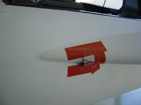
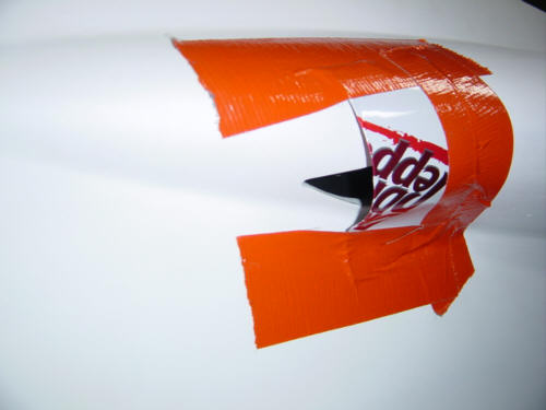
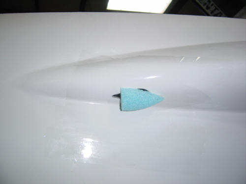
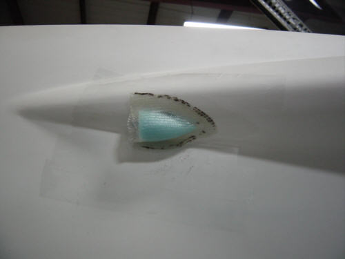
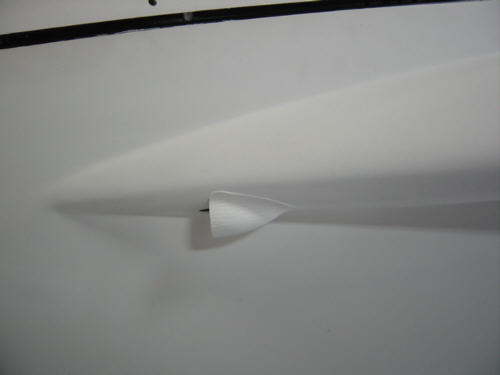
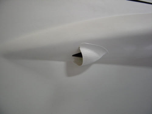
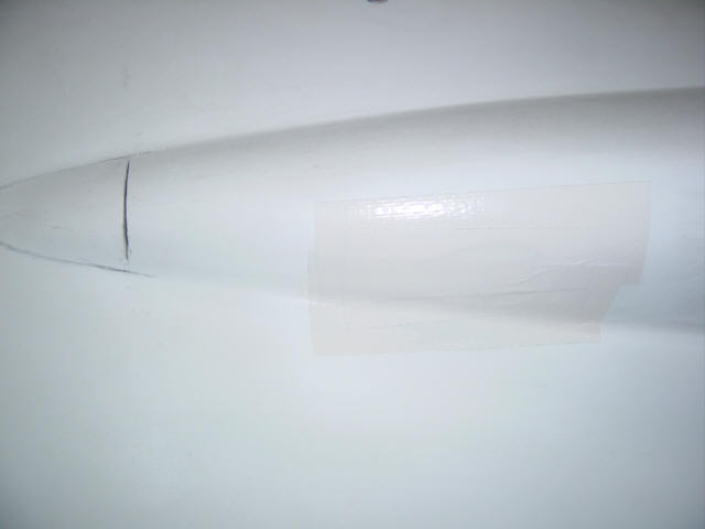
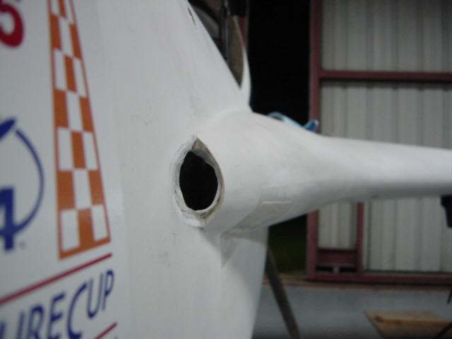
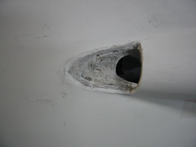
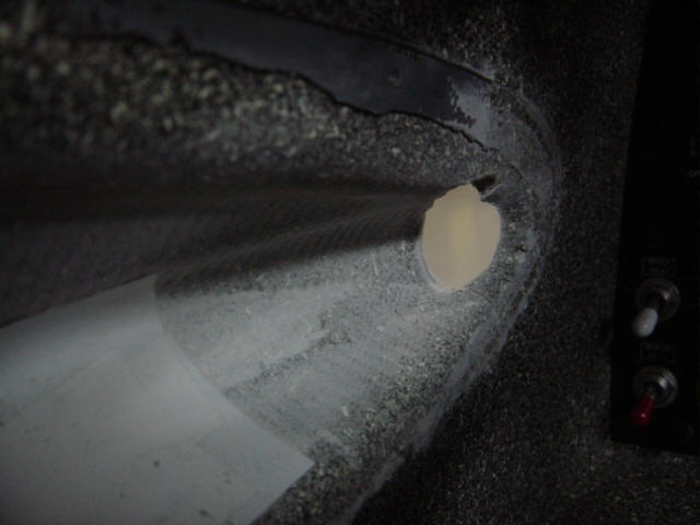
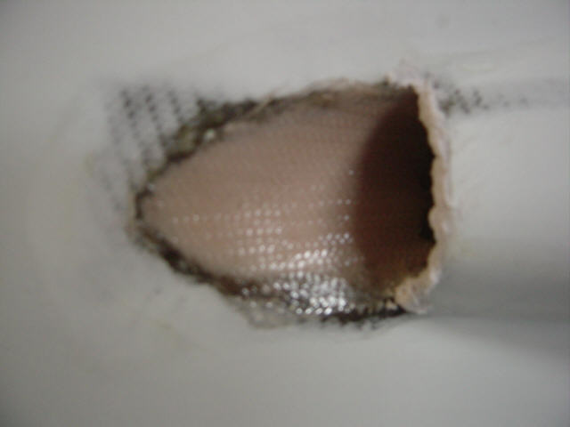
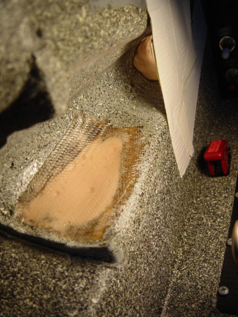
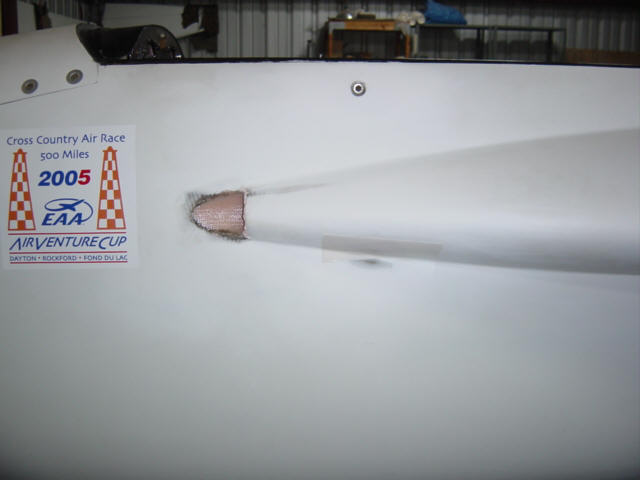
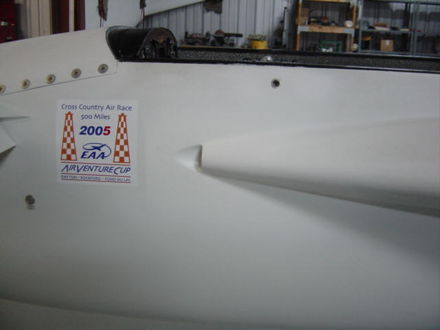
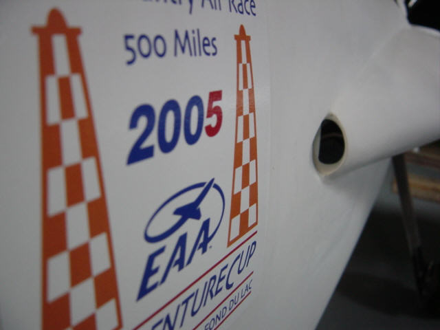
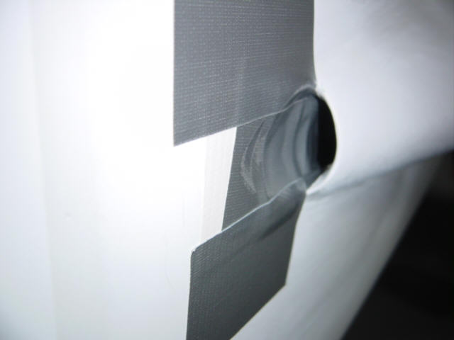
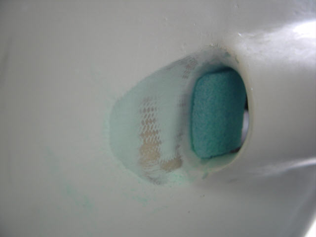
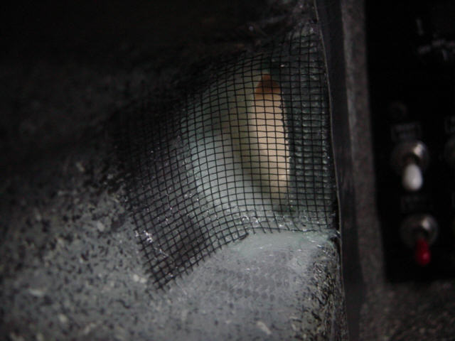
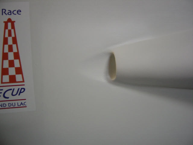
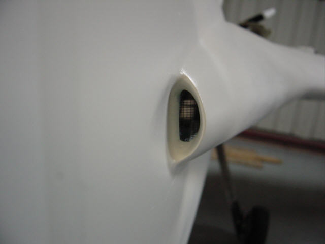
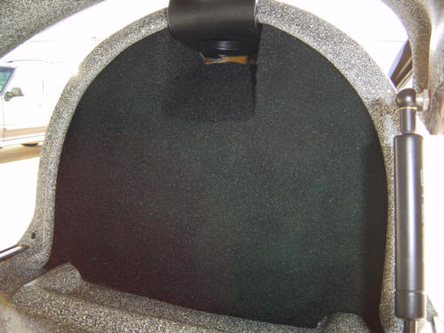
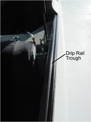
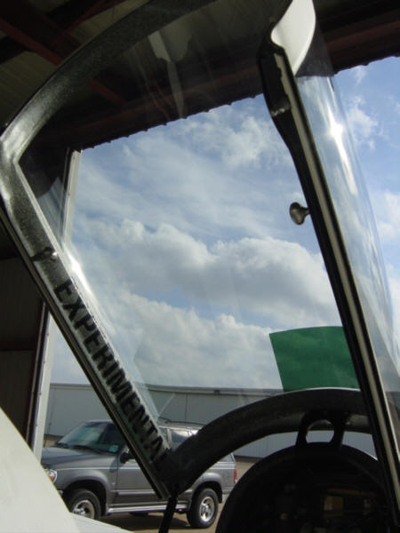
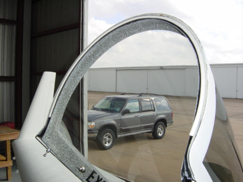
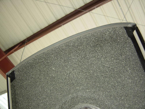
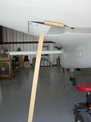
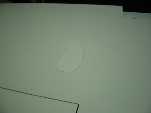
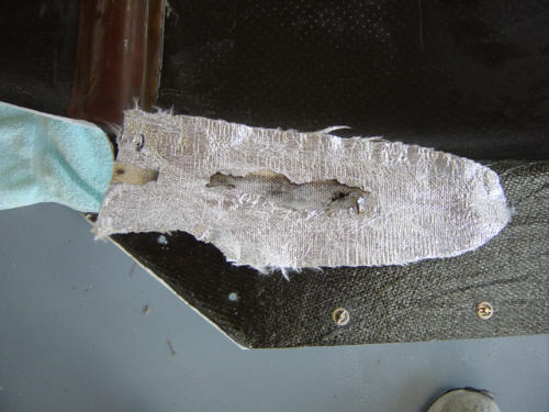
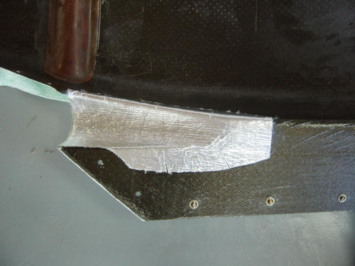
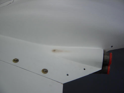
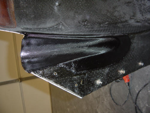
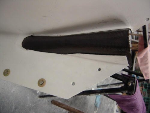
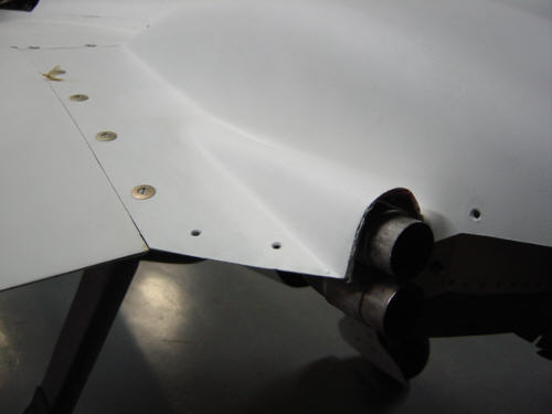
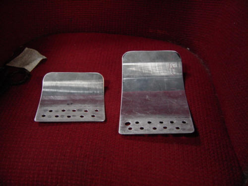
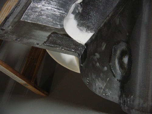
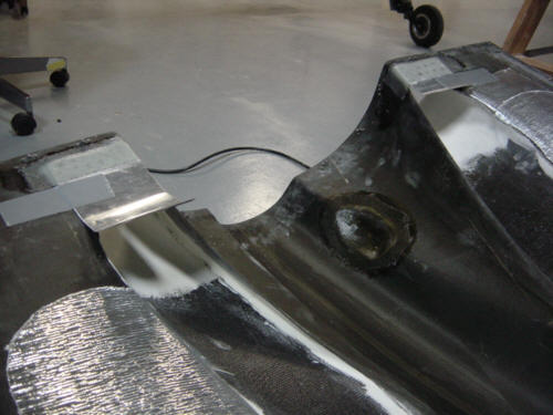
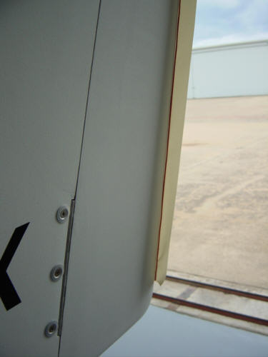
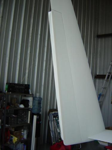
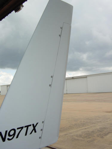
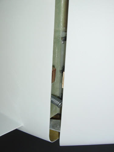
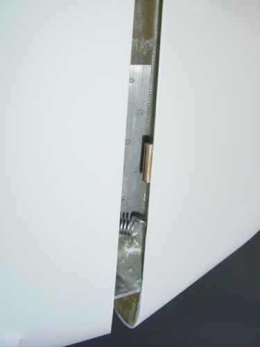
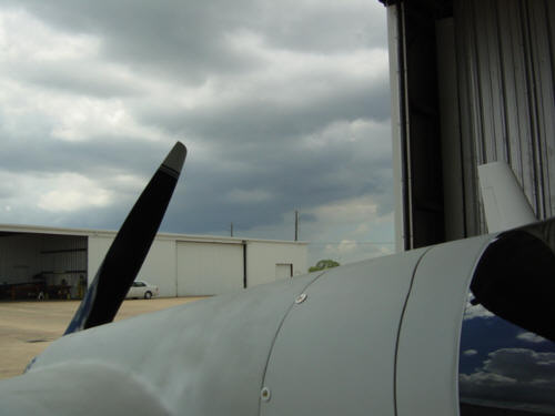
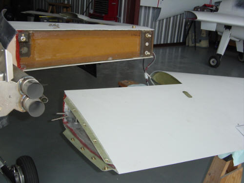
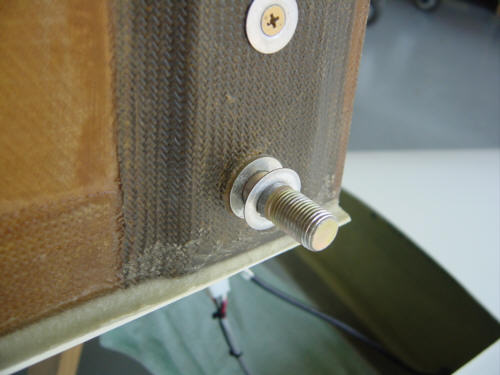
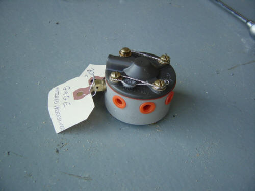
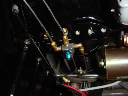
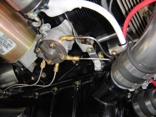
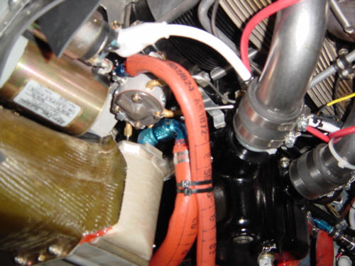
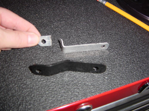
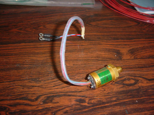
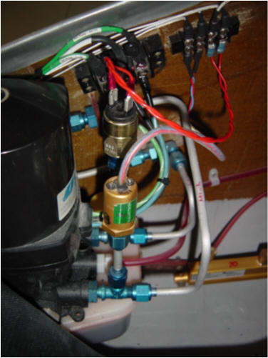
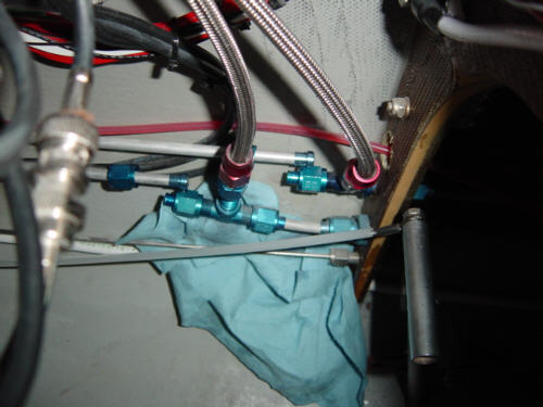
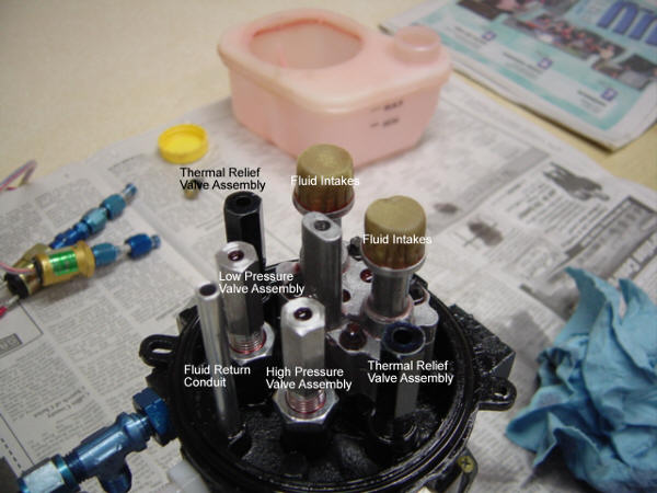
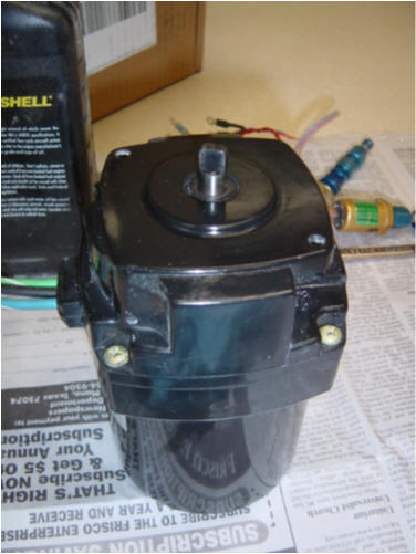
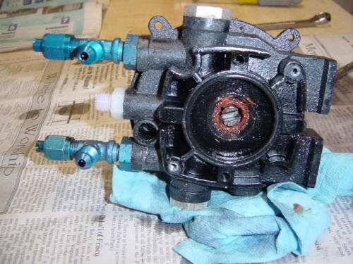
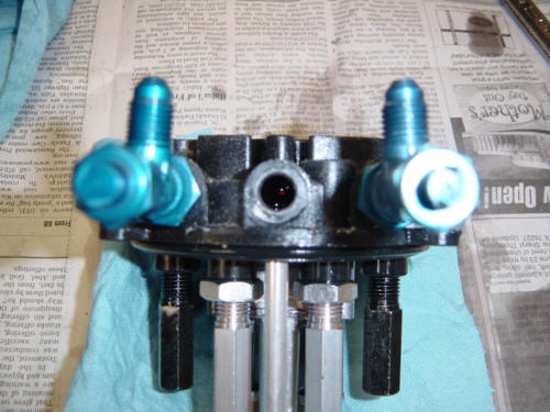
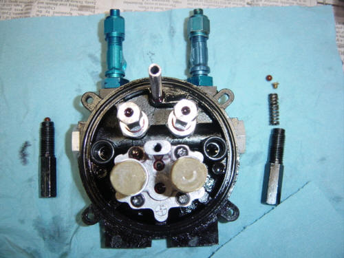
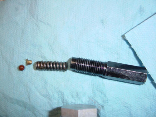
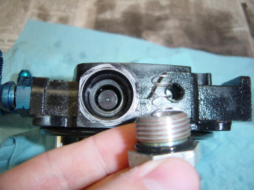
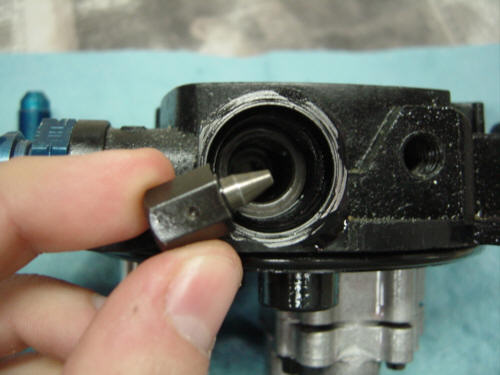
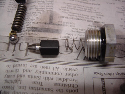
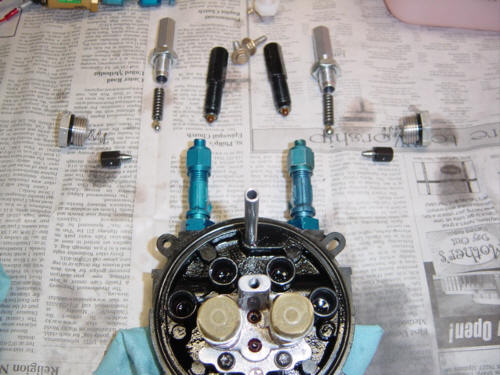
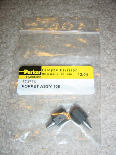
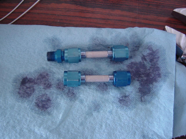
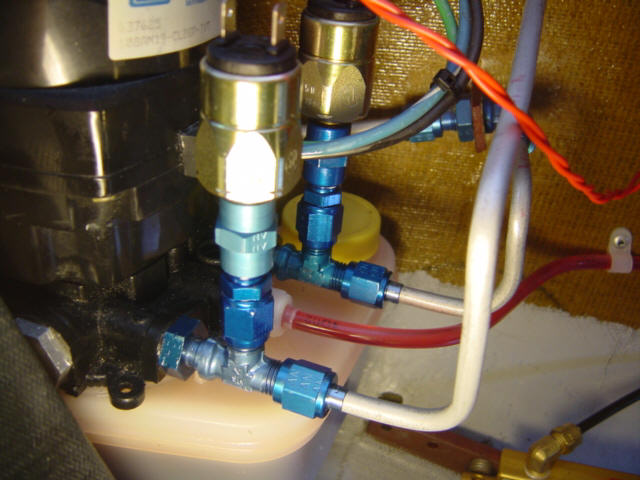
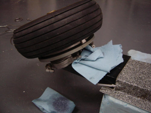
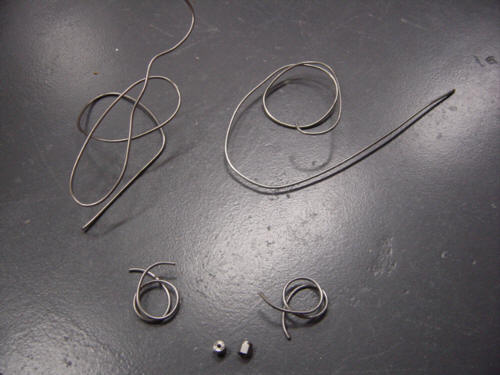
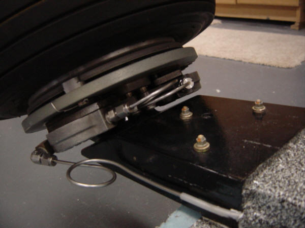
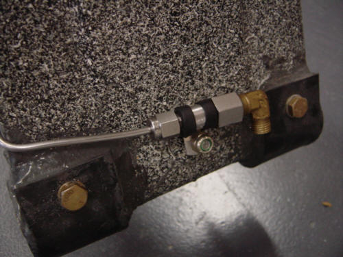
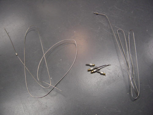
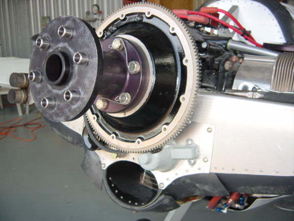
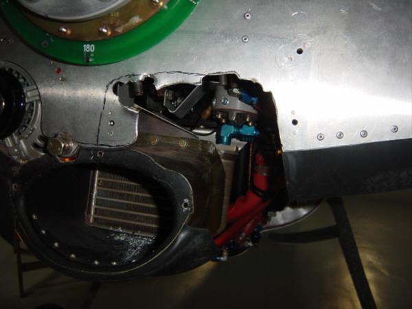
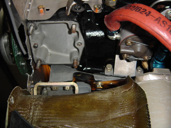
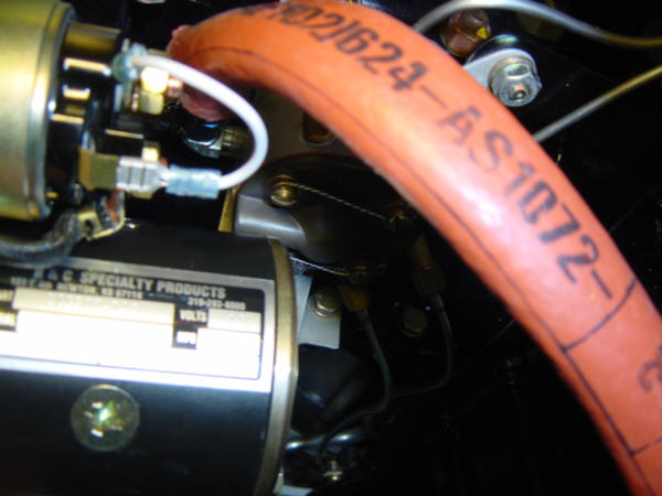
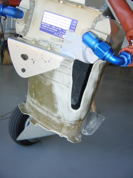
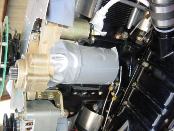
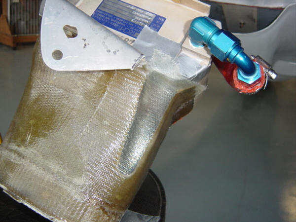
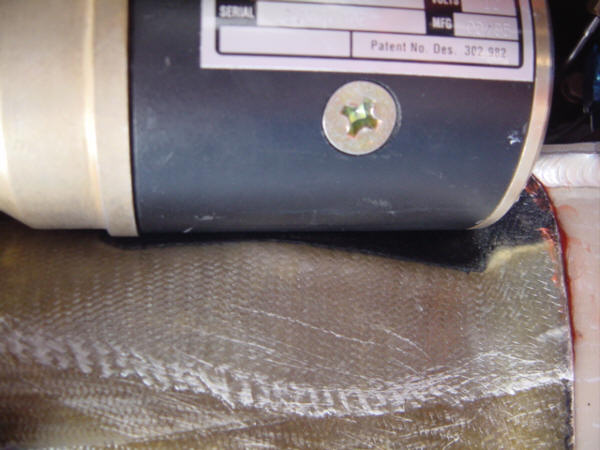
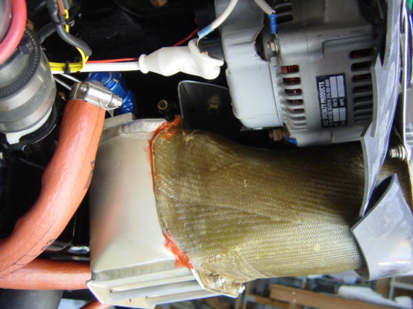
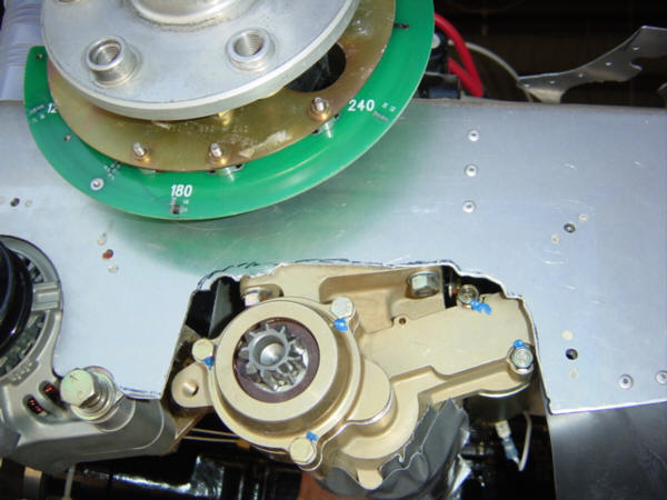
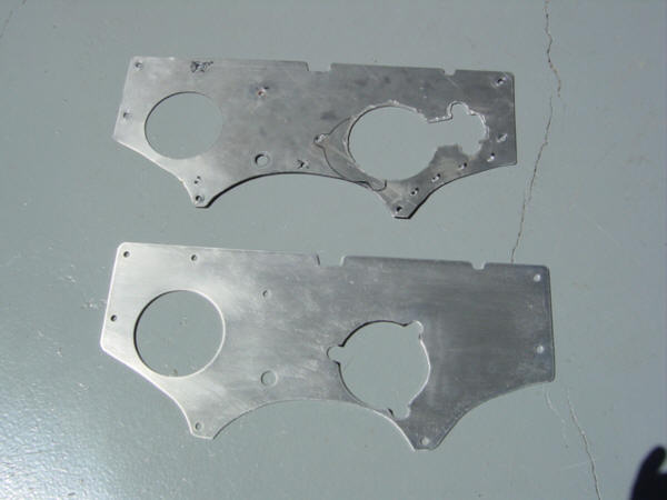
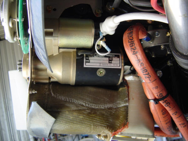
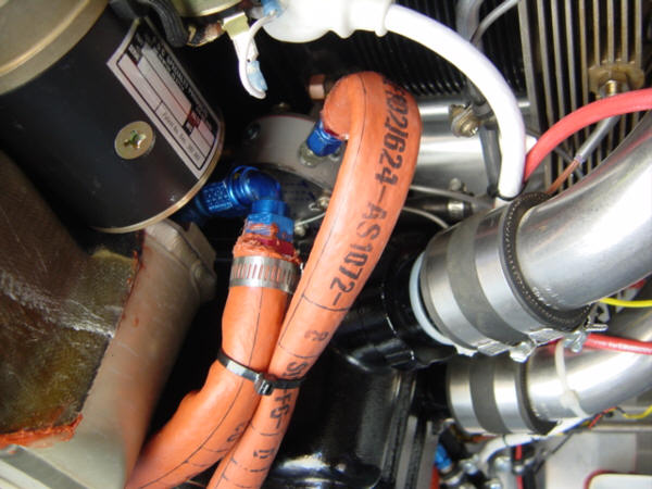
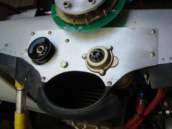
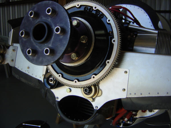
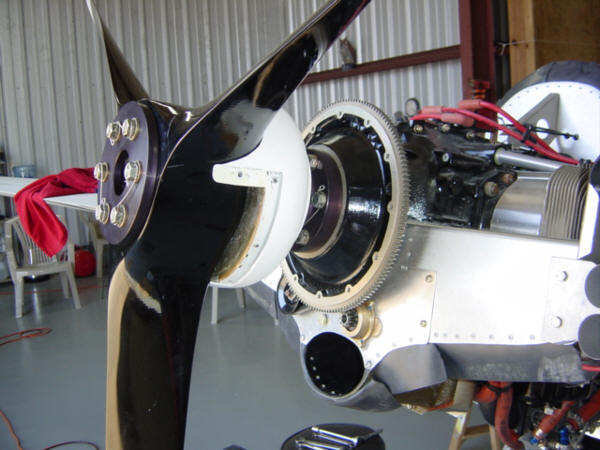
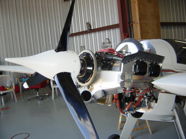
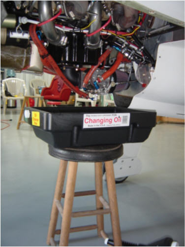
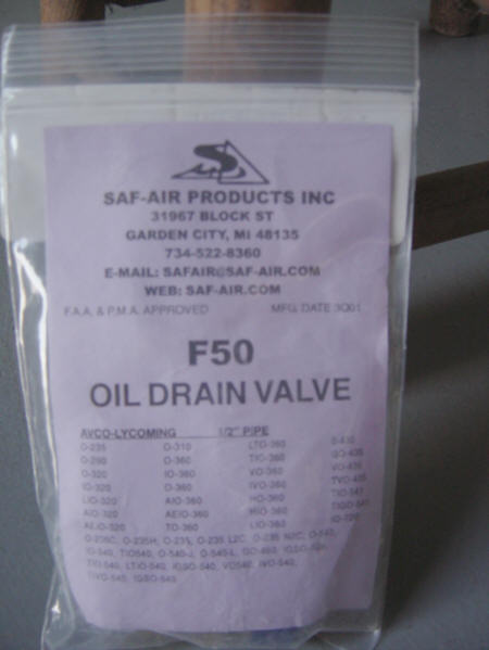
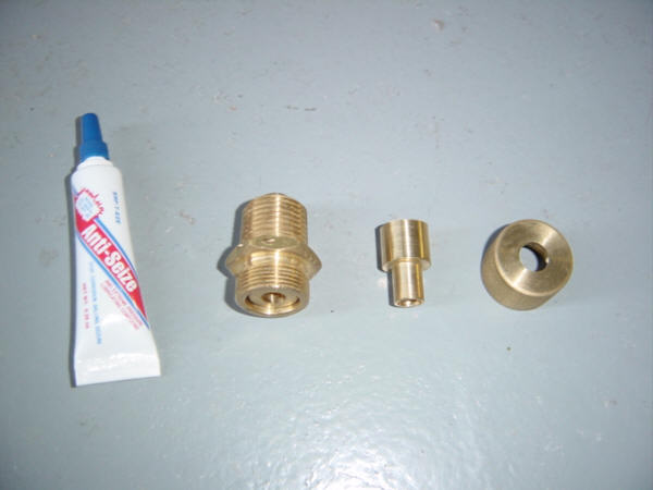
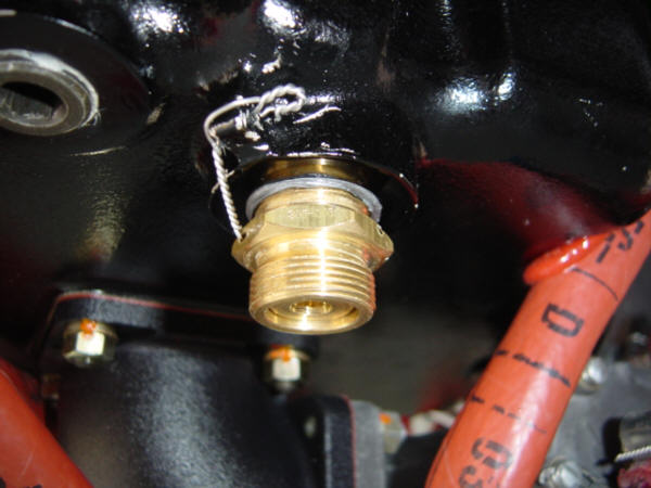
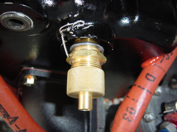
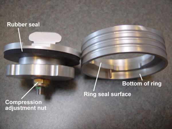
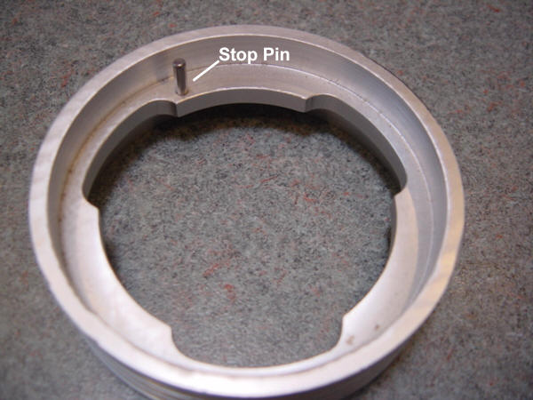
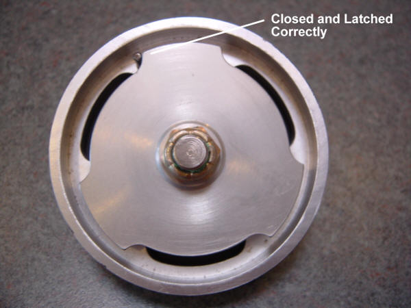
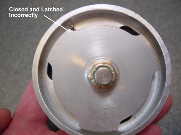
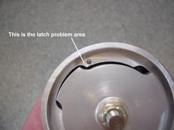
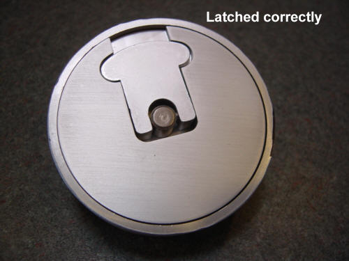
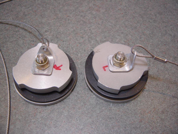
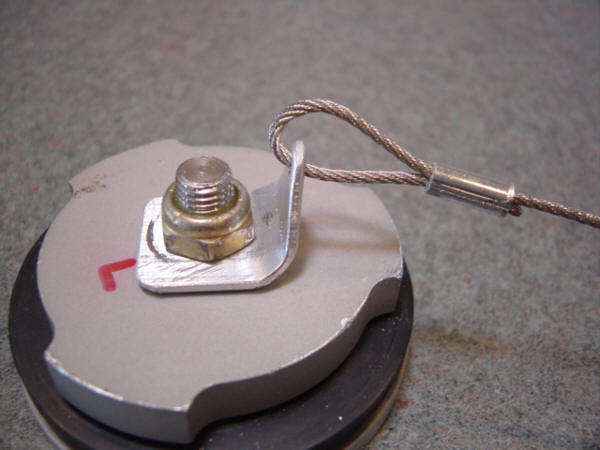
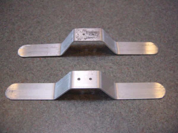
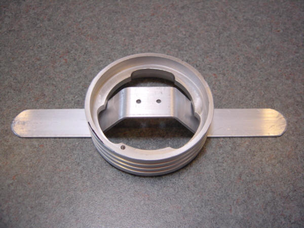
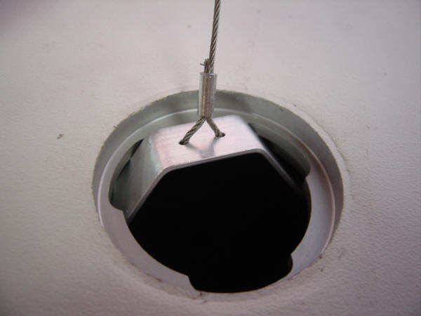
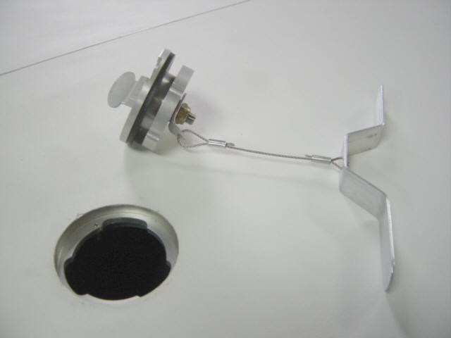
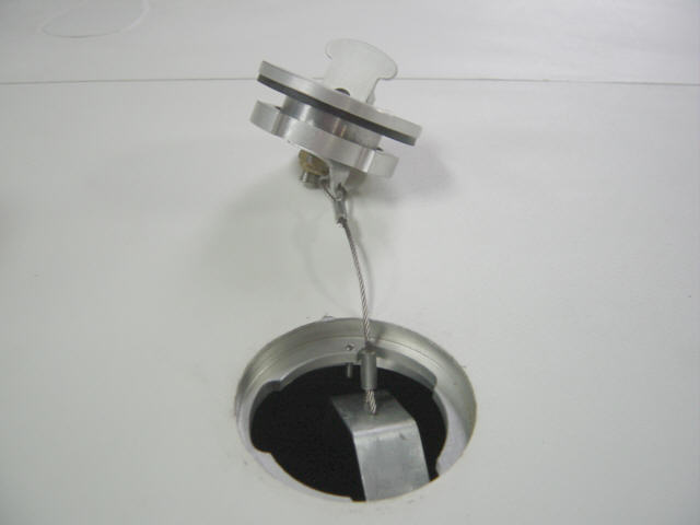
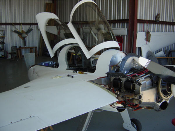
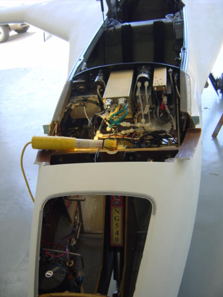
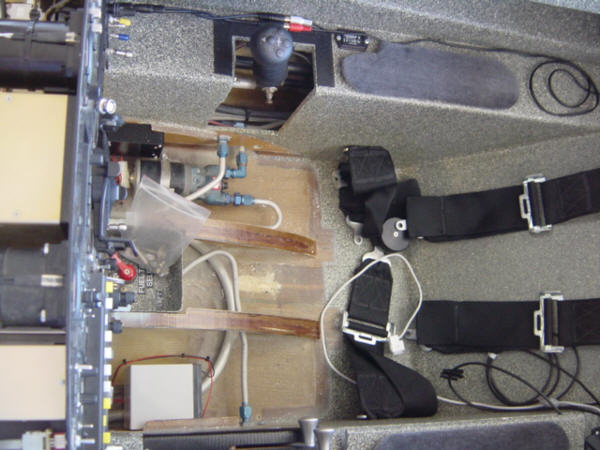
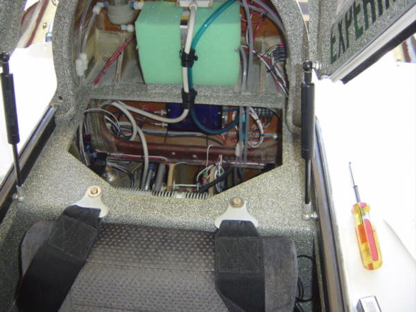
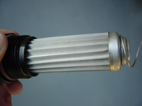
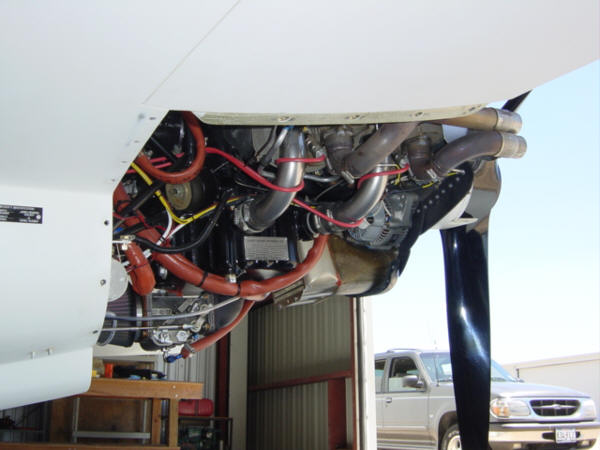
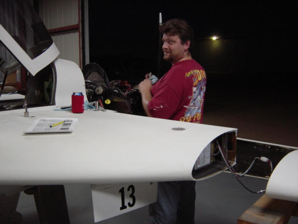
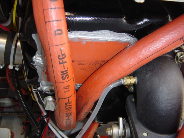
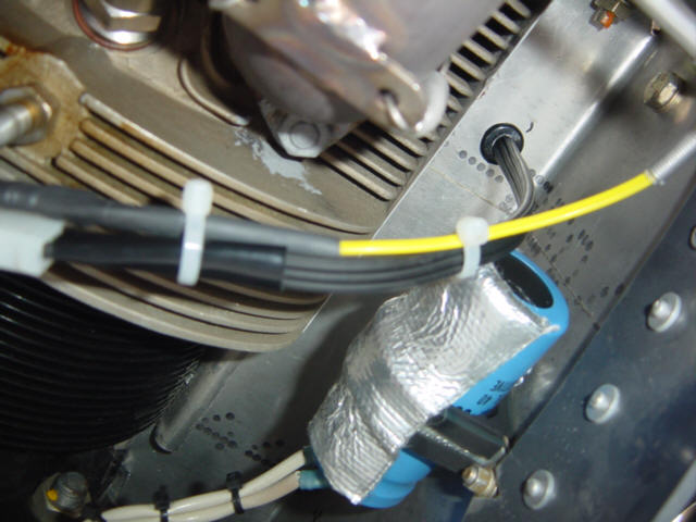
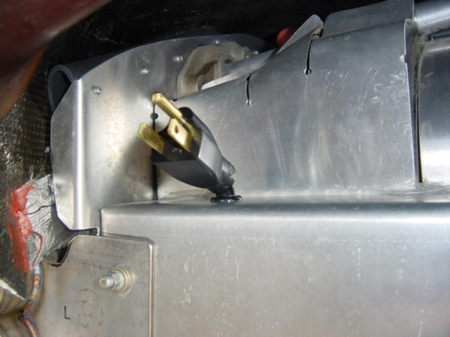
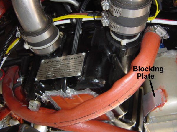
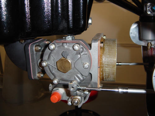
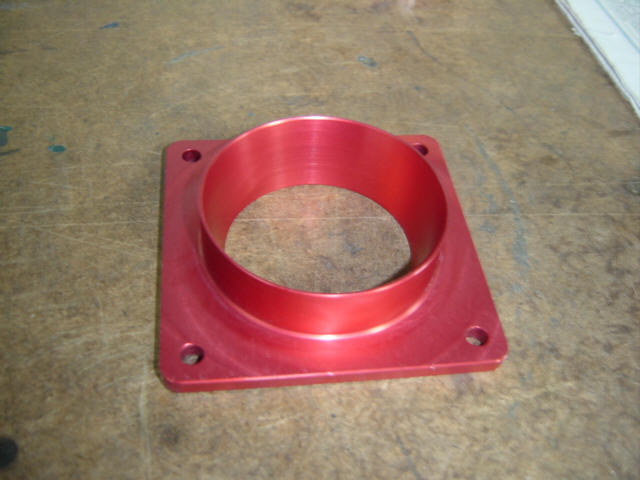
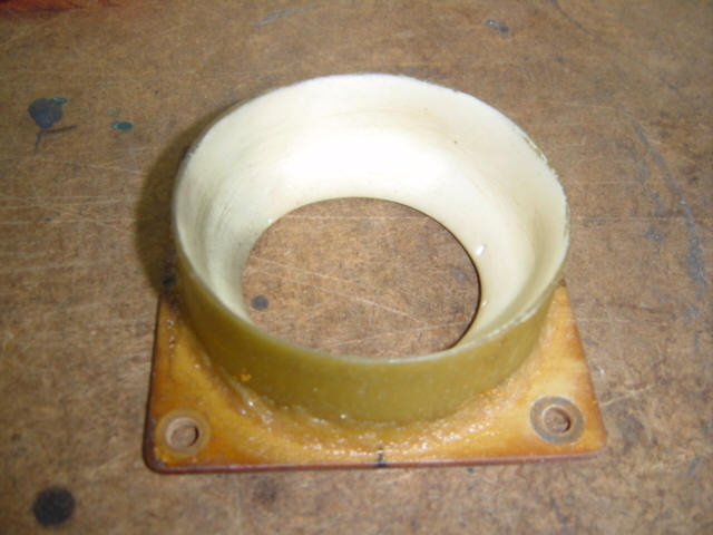
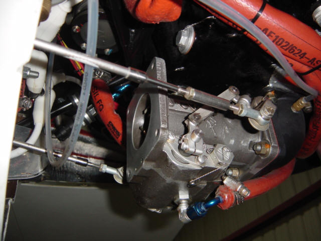
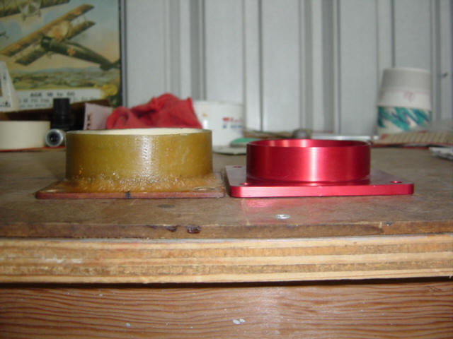
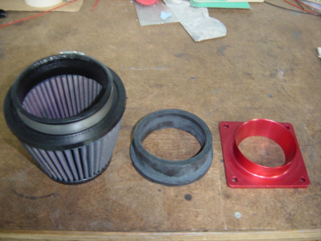
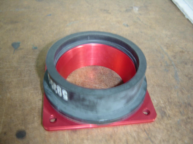
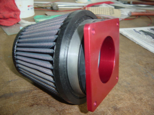
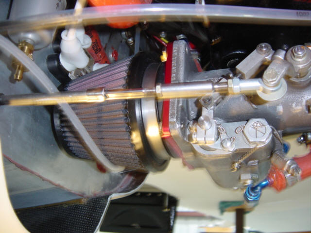
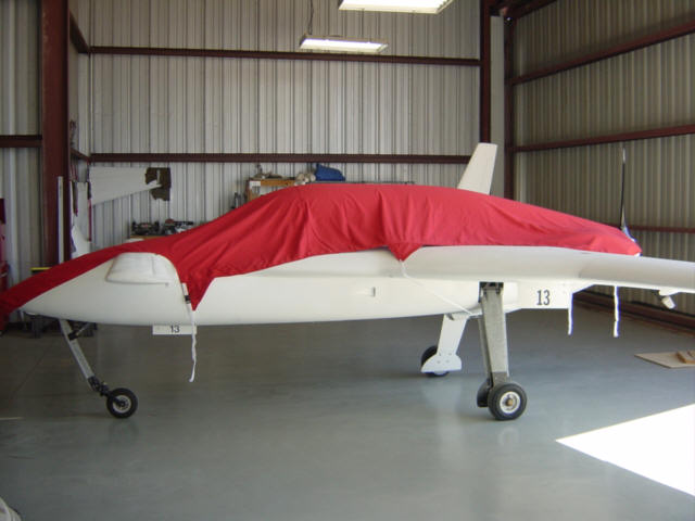
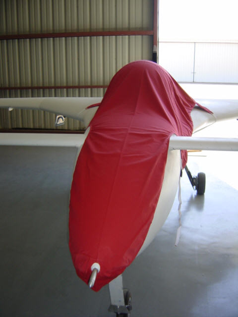
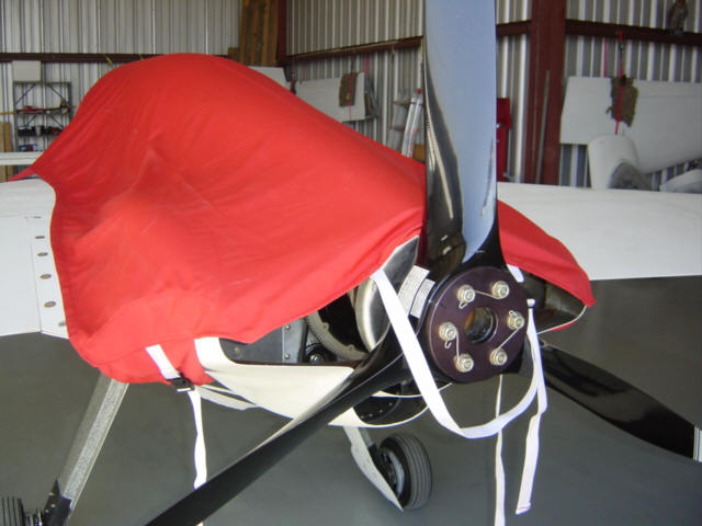
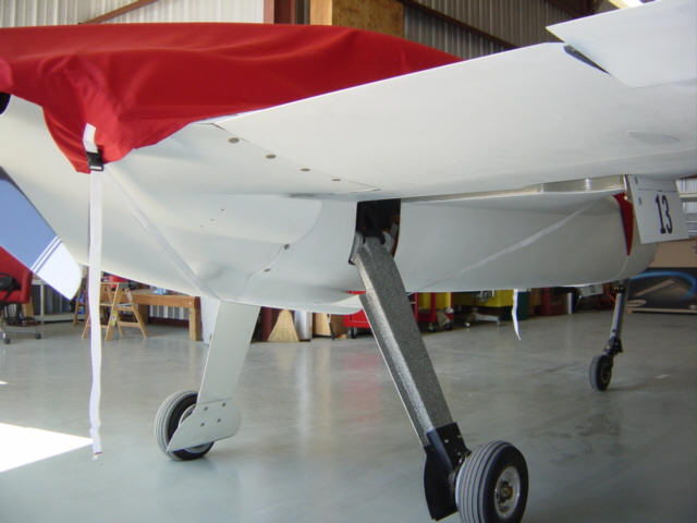
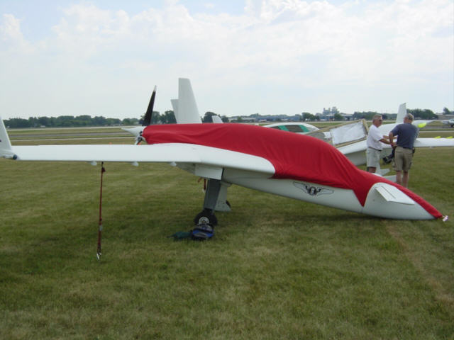
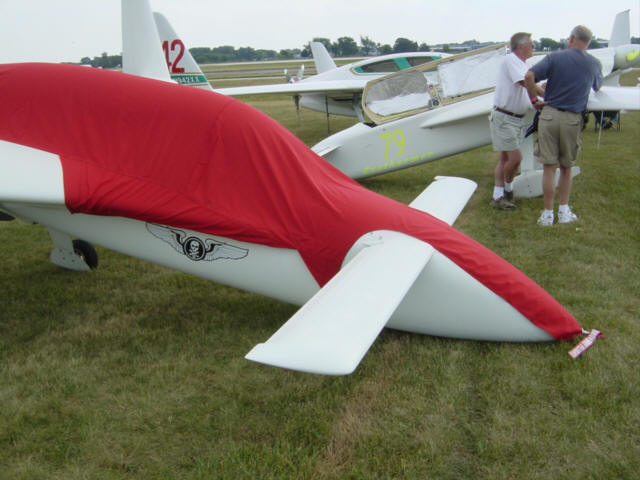
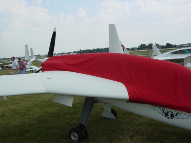
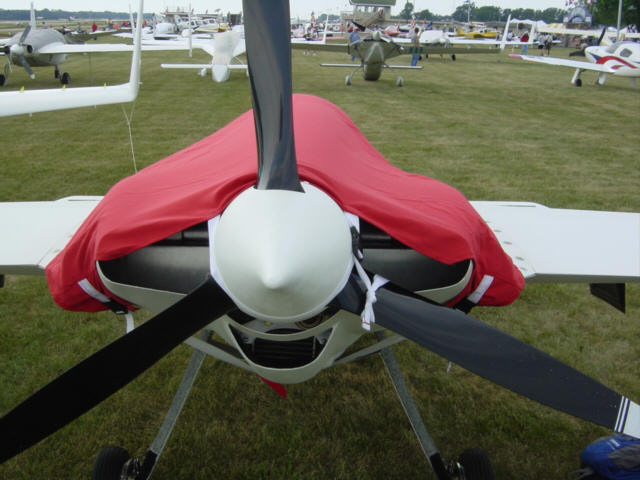
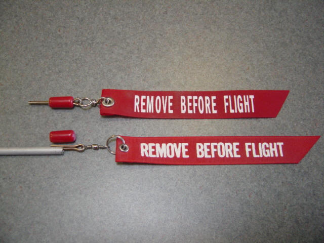
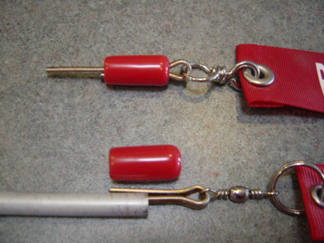
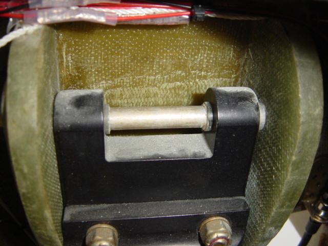
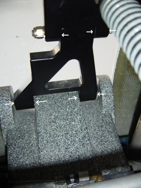
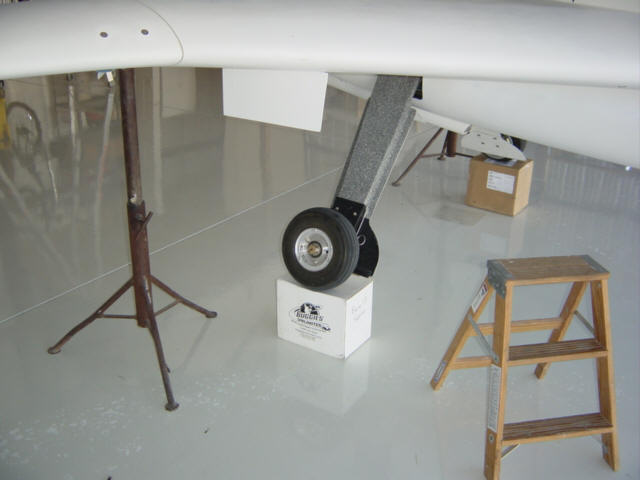
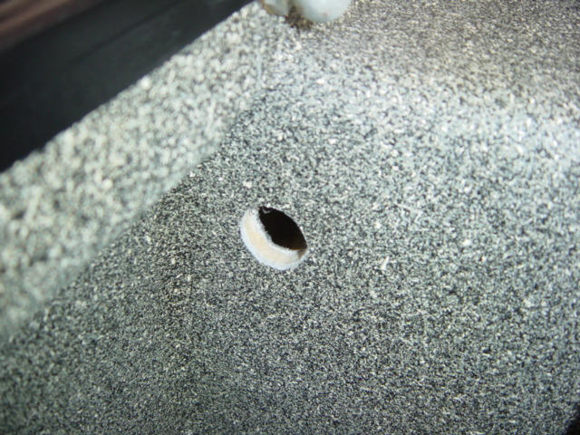
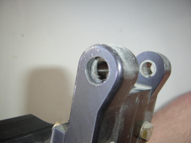
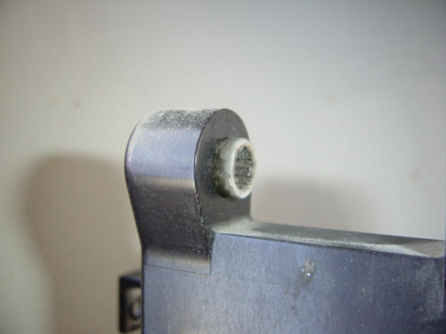
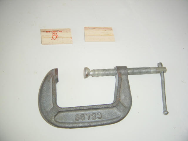
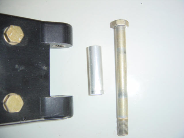
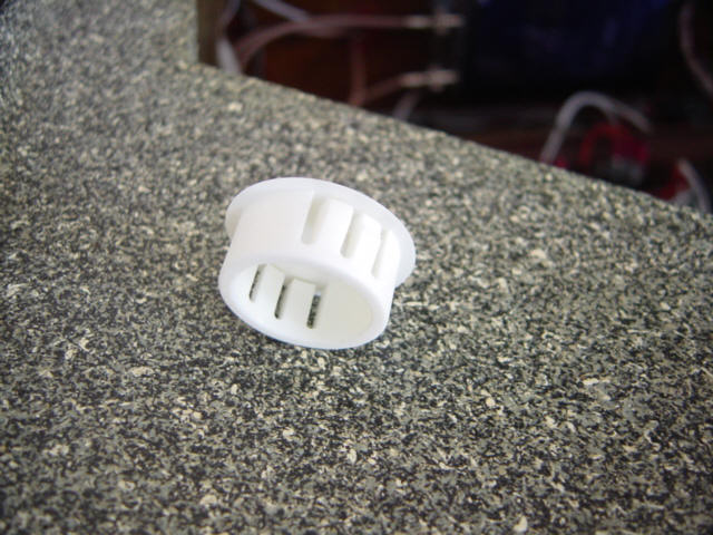
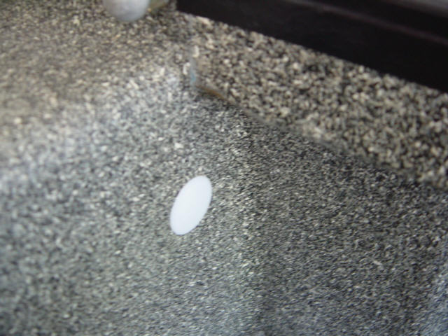
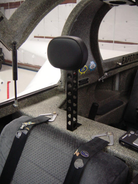
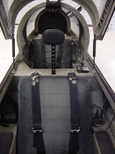
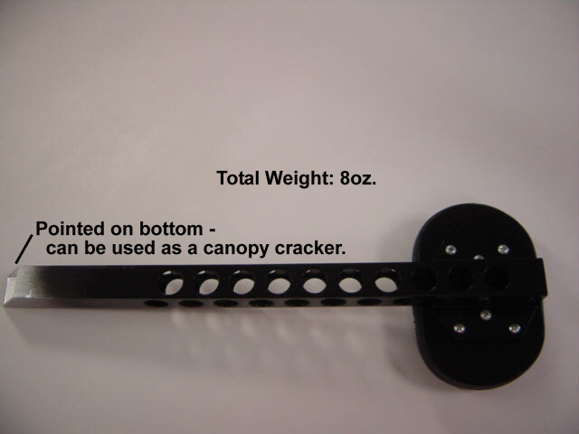
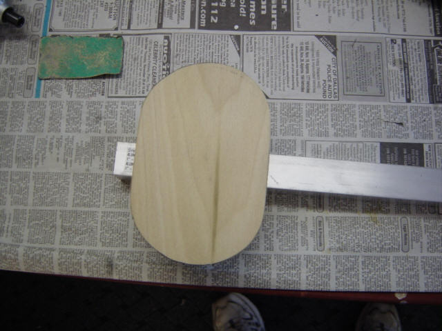
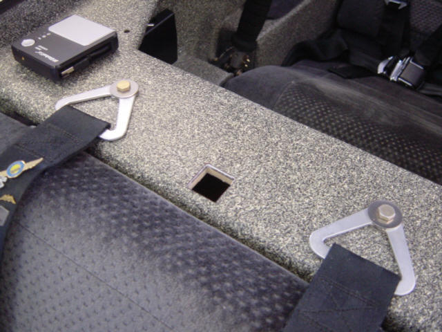
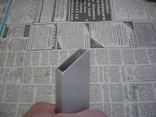
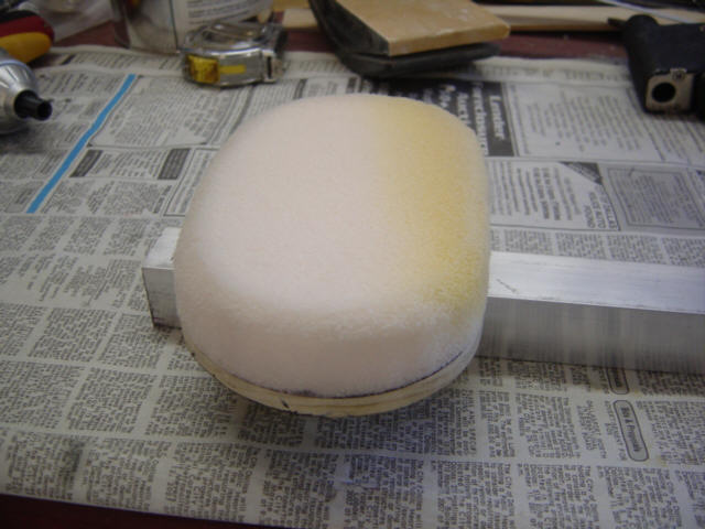
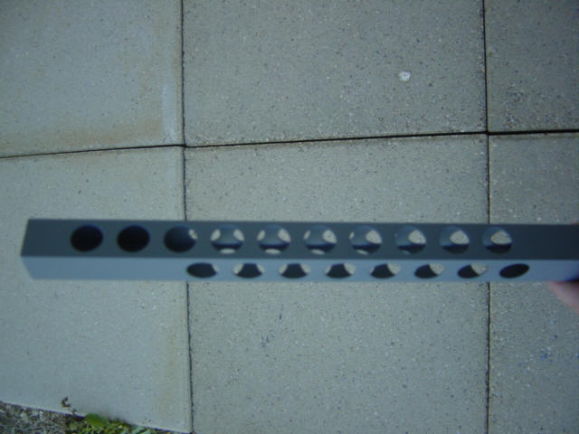
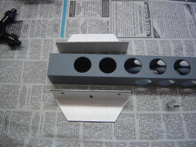
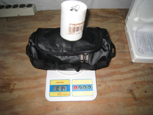
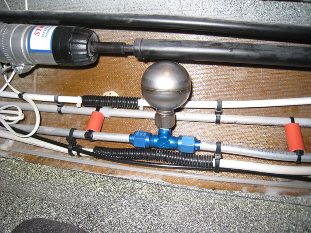
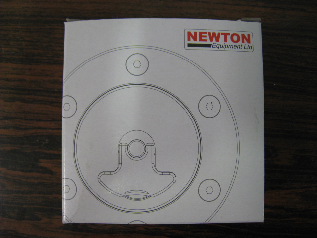
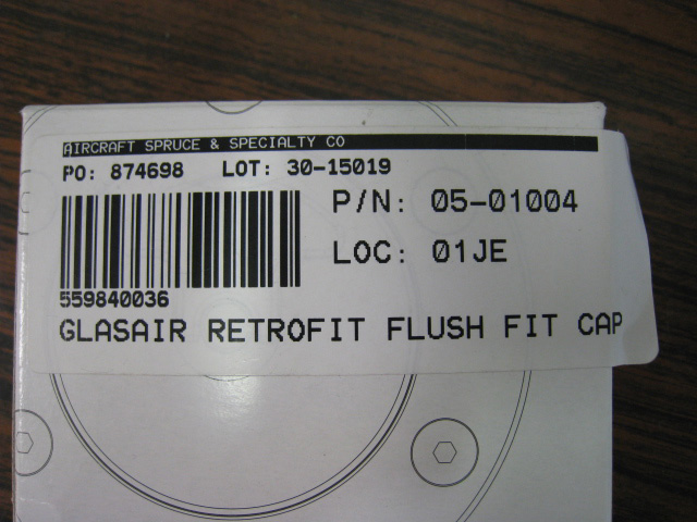
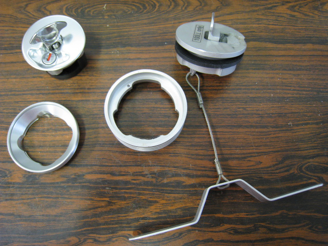
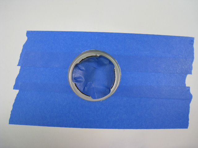
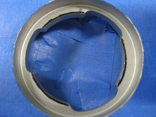
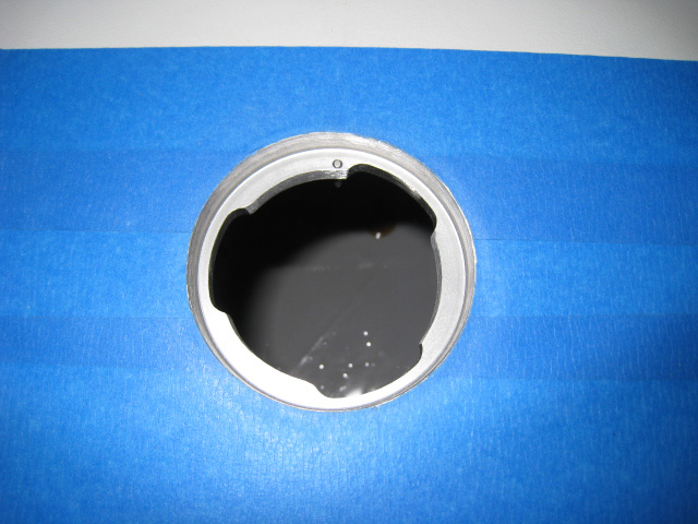
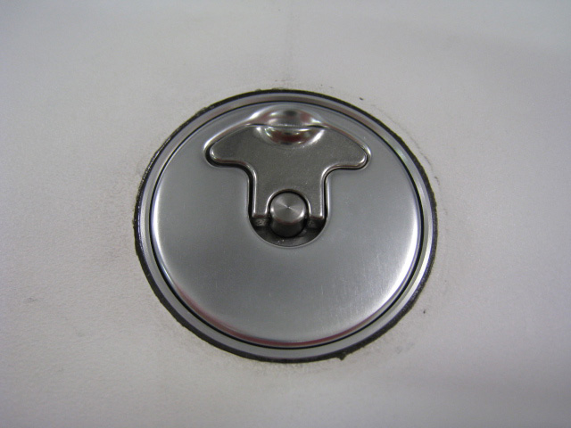
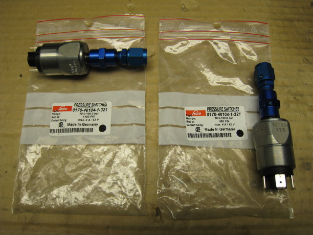
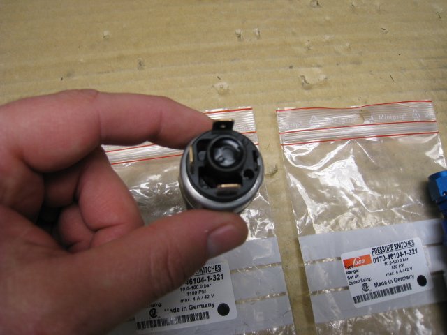
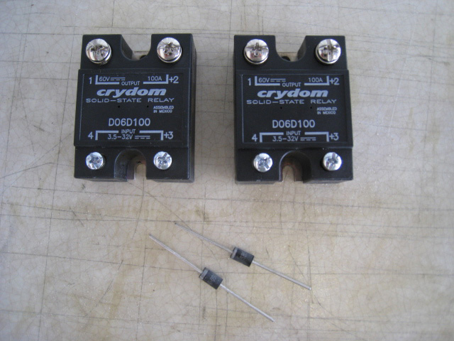
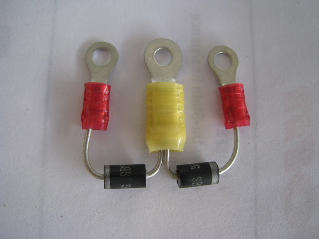
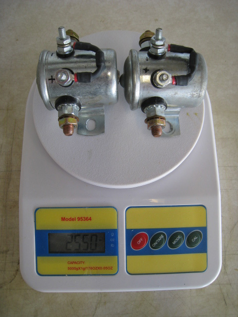
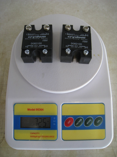
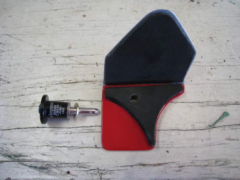
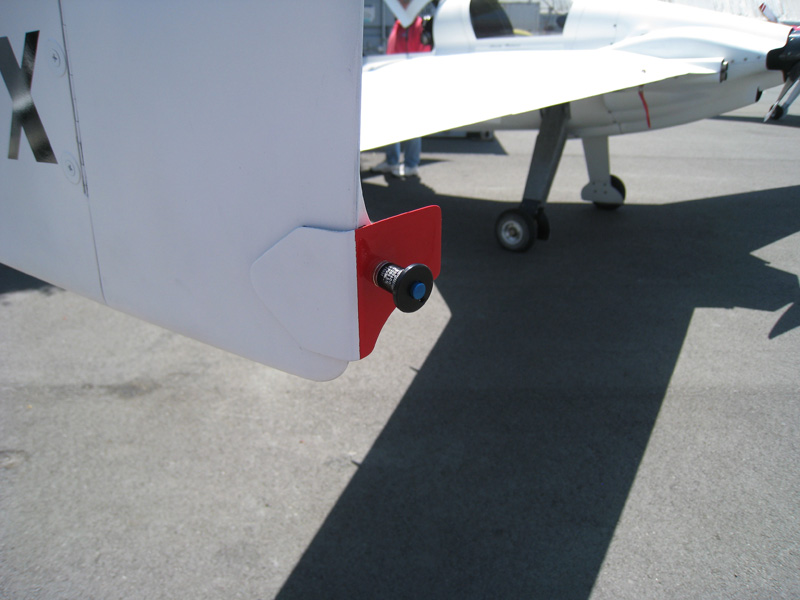
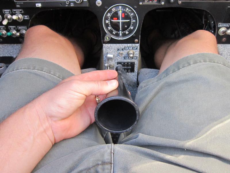
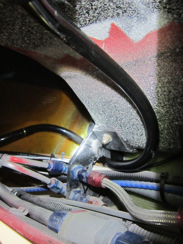
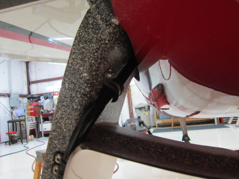
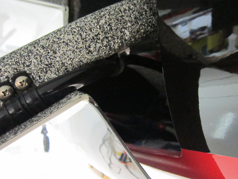
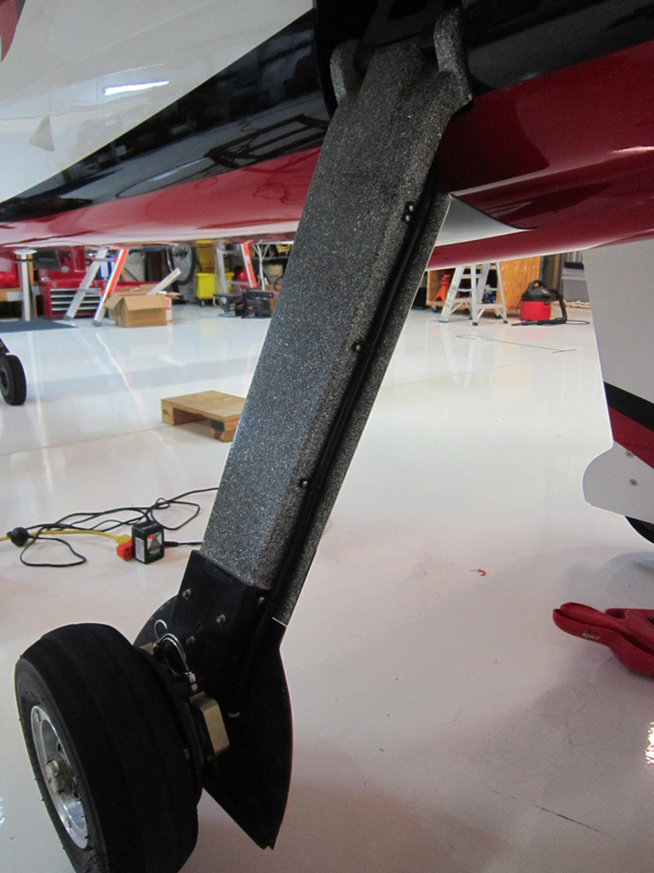
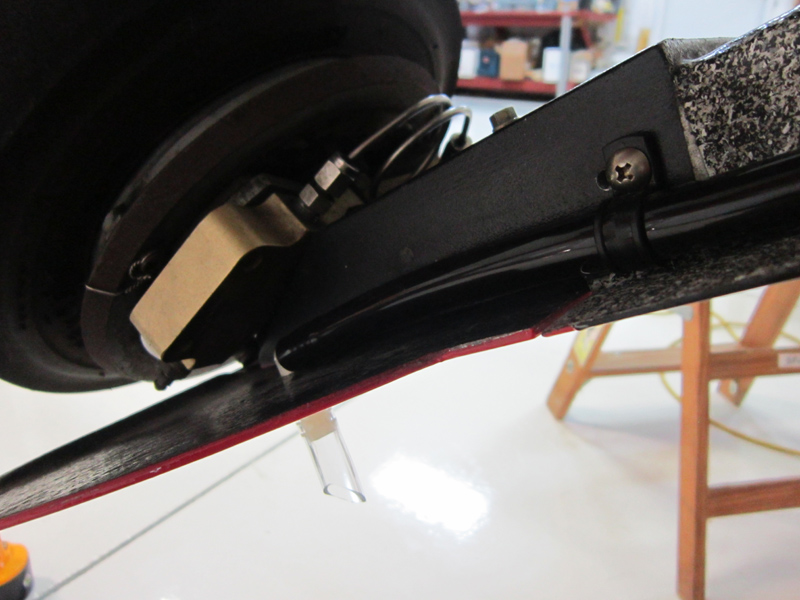
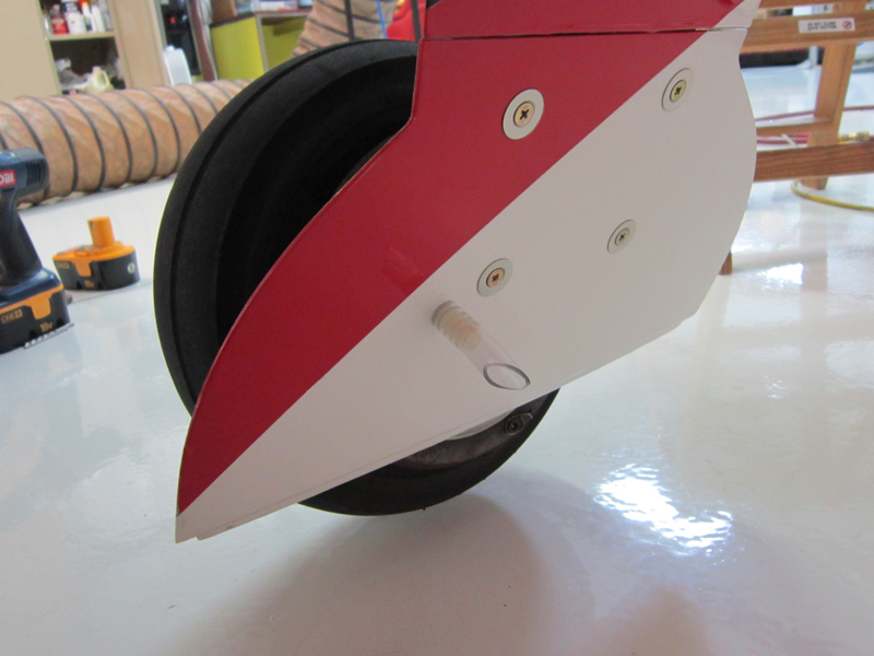
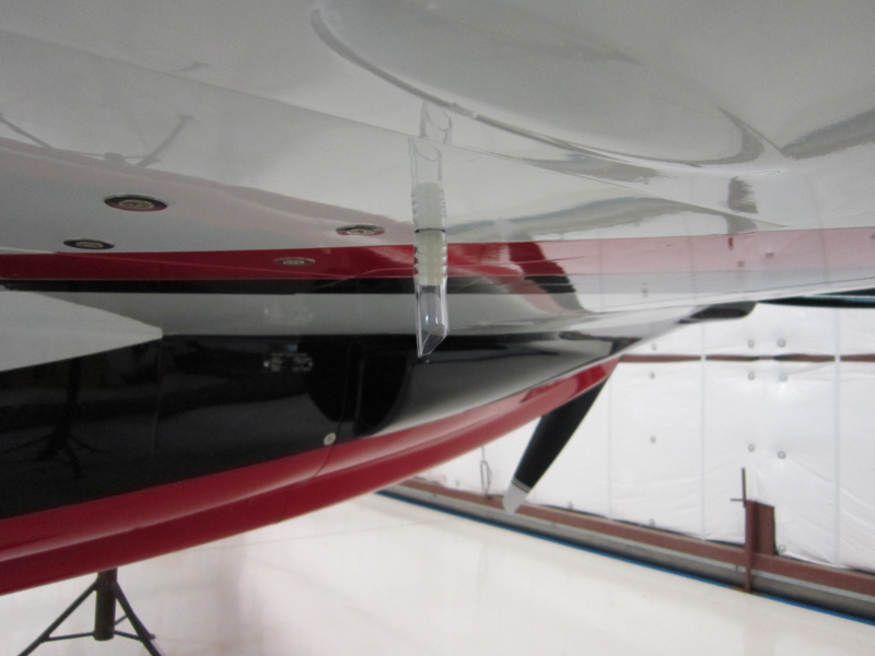
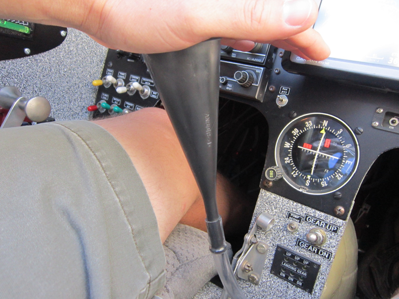
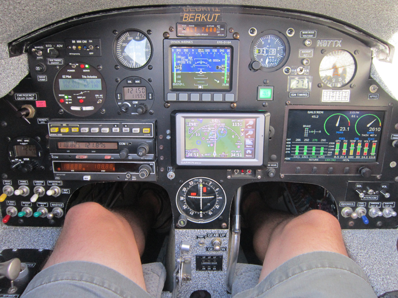
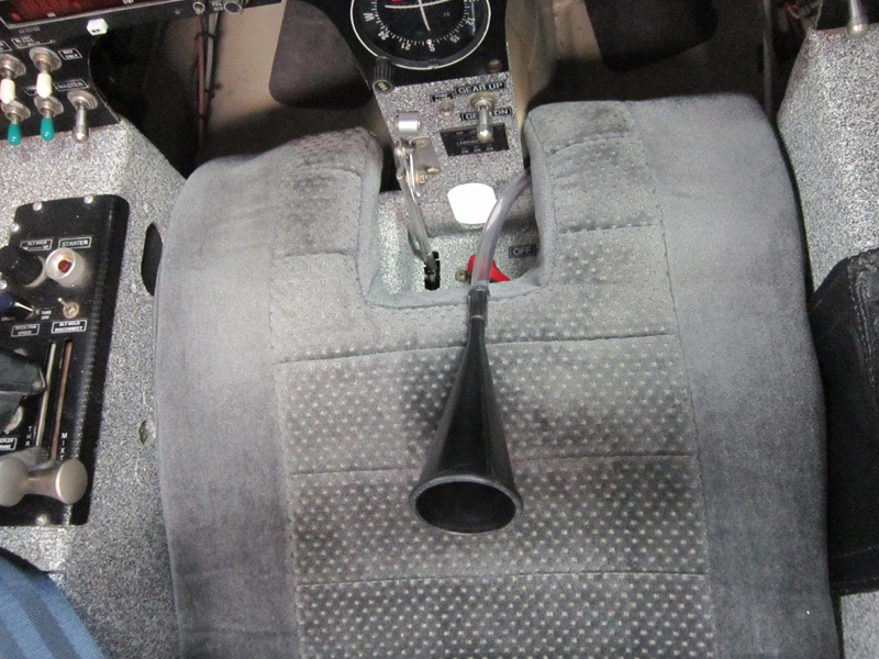
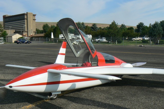
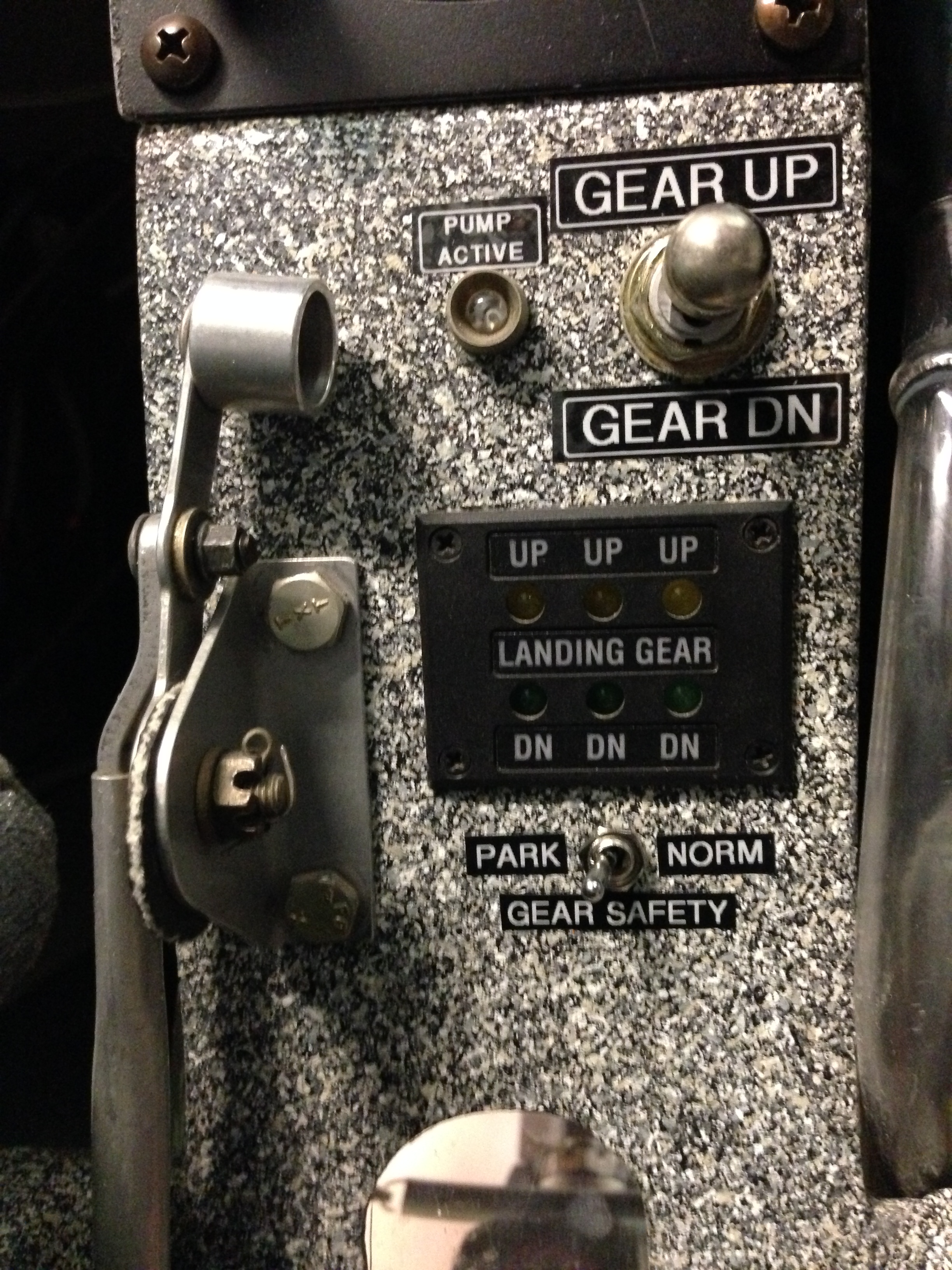
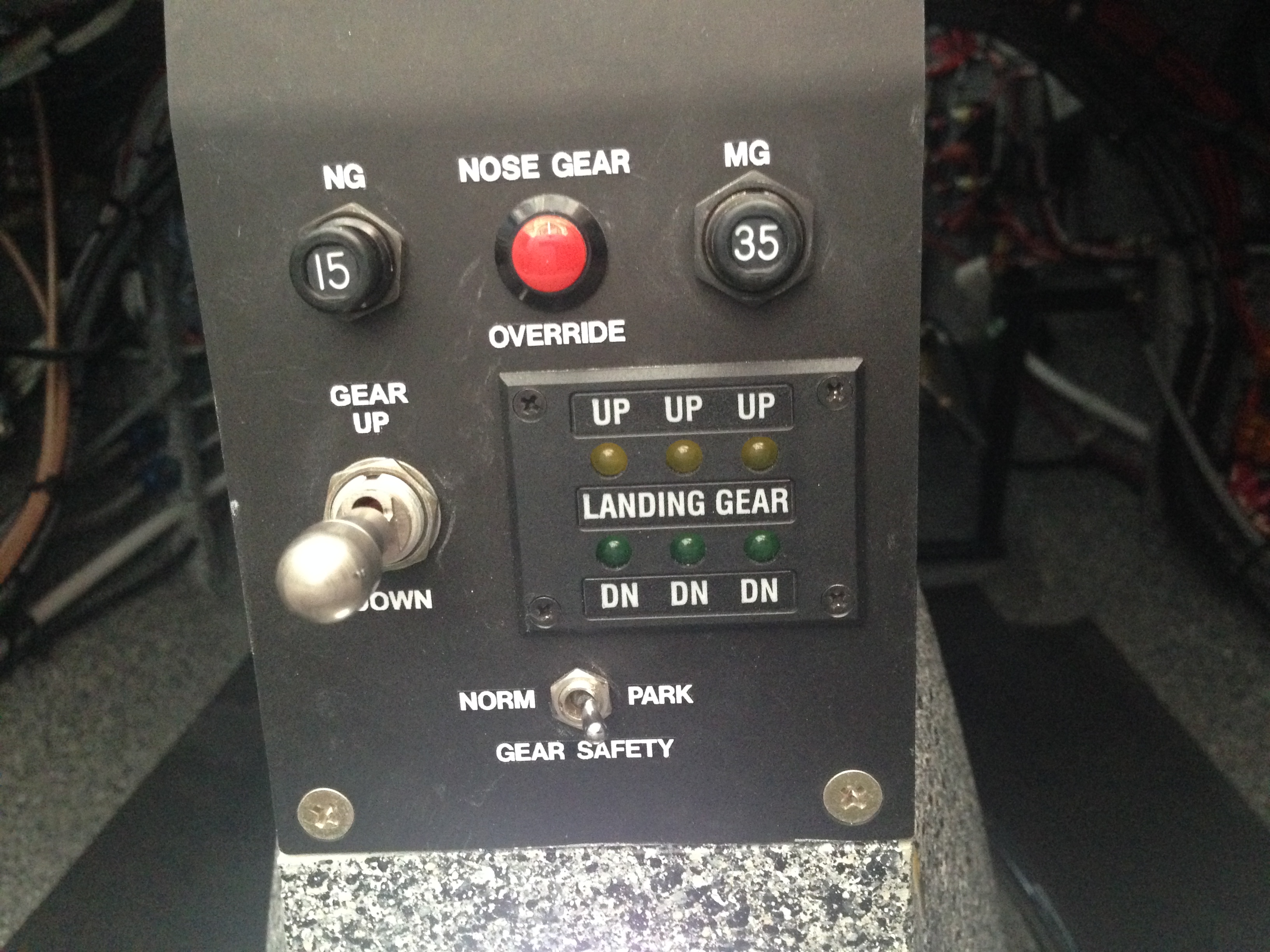