Yep, you heard right...'into' the canard - well, sort of. Here is where I get to tell you about a little oversight a few years ago. Back when building the canard, I should have installed this antenna under the glass skin but for some reason it was not in the plans. So, I blissfully completed the canard up to and including the micro fill. Luckily, Dave had come up with a work around that was just as good as an internal antenna. SO, here goes...
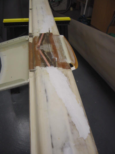
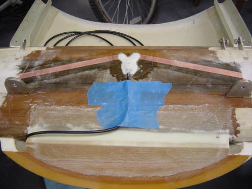
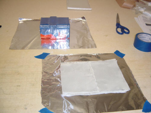
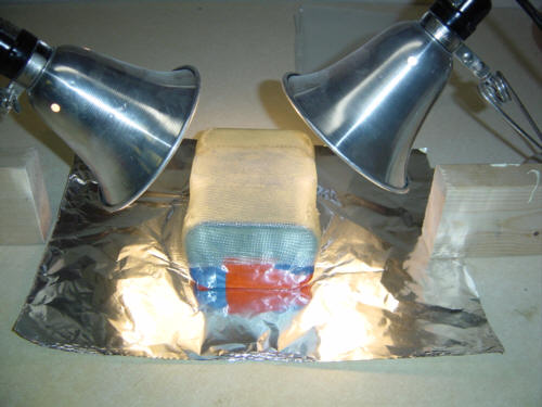
With the canard up on some saw-horses flipped over - I sanded out a slight depression into the existing micro to make room for what comes next. Then I attached the 22.8-inch, 1/2-inch wide, adhesive-backed, copper tape antenna legs into the depression. Then I covered it with some light weight glass BID and left the inboard 1/2-inch or so exposed for attaching the coax leads. (The BID is so thin, you can hardly see it) This glass ply is just there to protect the copper from damage while sanding the micro. And, speaking of micro - after the BID semi-cures, it's time to slap some micro over the outboard legs of the antenna. Since all of this was placed in a depression, there was no bump on the bottom of the canard after the micro is all sanded out. Lastly, the end of the coax cable is stripped and soldered to each of the two legs of the copper antenna - one attached to the core, the other is attached to the cable shielding. And to make it all secure, the solder joints and the 3 torroid beads are covered with micro and one ply of regular BID. This antenna will now serve as both the navigation (VOR) as well as the glideslope (ILS) antenna. I will attach a signal splitter in-between the antenna and the two radio inputs.
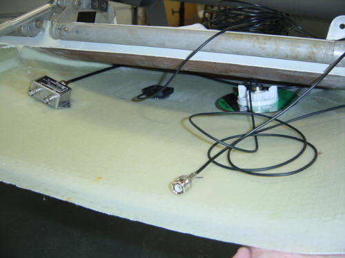
UPDATE 5-16-04: I finally got around to installing the GPS antennas in the canard deck. They are simply RTV siliconed to the canard deck fairing. In that picture, the canard was upside down. The very small one is for the EFIS-Lite (GPS cross-linked inertial sensing) and the larger one is for the Garmin 196. Also shown is the antenna splitter used to seperate the Nav and Glideslope signals for the radio. Why they could not jsut do THAT inside the radio itself...I'll never know.
Sorry. This antenna was actually installed some 10-years ago when I first started the project...and I have no pictures of this procedure. However, it basically follows the same process as the NAV antenna but is placed into the winglet foam and covered with the actual winglet skin plys. Fiberglass and foam is invisible to radio waves, so it is as if the winglet was not even there. In case you are wondering why we go through all these steps to install an antenna instead of just bolting one on...one word...DRAG! Simple: no antennas in the wind...no drag.
That, and the plane looks so sleek that any little bump or 'whisker' will detract from the lines.
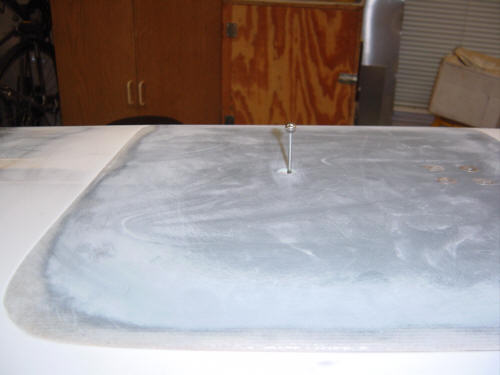
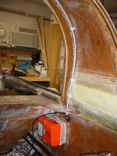
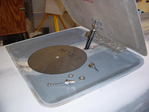
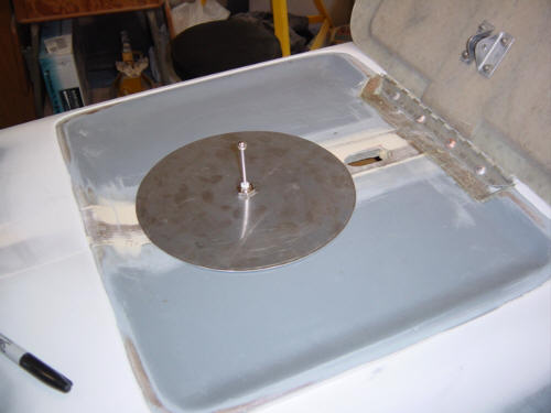
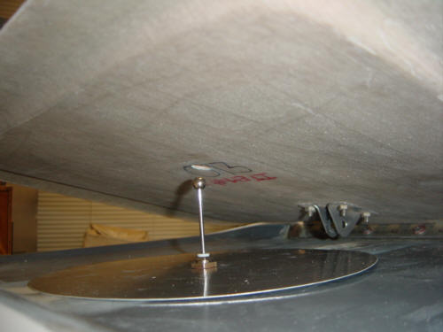
OK, you got me...there is ONE antenna that sticks out of the plane - but only a little. The short transponder antenna is mounted to the bottom of the fuselage and protrudes through the belly brake. The fuselage and the brake are constructed of fiberglass, so the microwaves will pass right through them as if they were not even there. However, that means we do have to ADD a ground plane to the antenna.
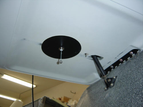
The ground plane is simply a 9-inch diameter aluminum plate. The antenna is attached, through the ground plane, to the bottom of the fuselage underneath the belly brake. Now, what makes this install kinda kewl is the 1/2-inch hole drilled through the belly brake so that the antenna can stick through as the brake goes up and down. Nifty, huh!
UPDATE 7-25-04: I've been meaning to fix this for awhile and am just now getting around to it. According to the radio wizard Jim Weir, the ground plane for this antenna should be 5.5", not the 9" size referenced above. So, I trimmed it down to the proper size. One less thing to worry about...
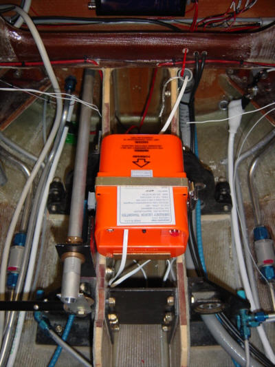
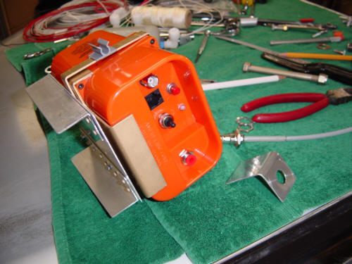
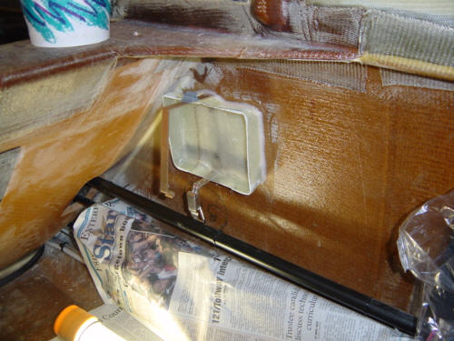
One antenna I installed I hope I never use - the Emergency Locator Transmitter (ELT). For those unfamiliar, all aircraft are fitted with these devices and in the event of a "hard landing", it automatically activates and transmits beacon signal that rescuers can receive and use to find you. The unit always mounts in the aft sections of the plane and in this case, is mounted right between the main gear bulkheads with a wire leading up to the remote status/activation hear on the instrument panel. I had to fabricate aluminum brackets for both the unit itself and the antenna. I didn't bother making a fancy copper tape dipole, I simply used the whip style antenna that came with the unit, slipped it into a piece of Nyla-flow tubing, and mounted the antenna bracket to the side of the fuselage. You will also notice the green wire coming from the base of the antenna bracket - that acts as a ground plane and should enhance the antenna's efficiency. After hooking it all up I waited around until the "first 5 minutes of the hour" to test it...and it comes through loud and clear. This Ameri-King 450 unit is also capable of being removed and used with an external portable antenna and can also transmit voice with an external mic. A handy unit...I hope I never use!
UPDATE 4-25-04:
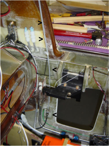
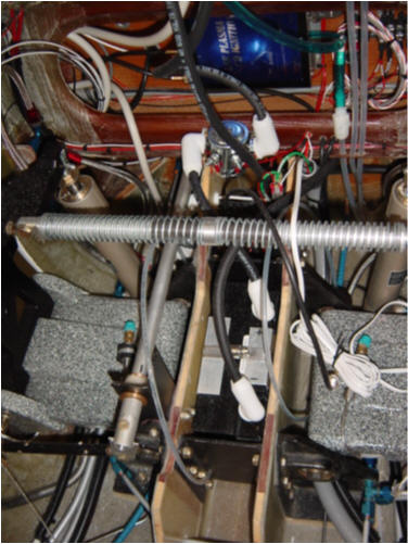
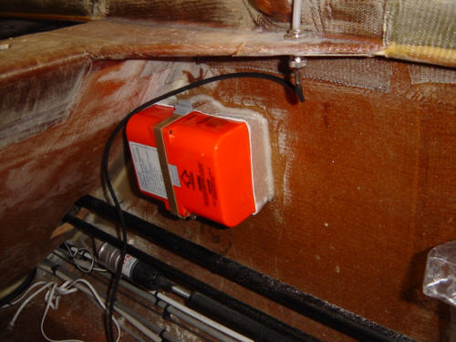
Well, Crap! Here we go again...yet another time killing re-work session. As you can see from the above picture, I originally installed the ELT in the aft compartment between the MG-30s. When I tested the engine, I determined I had to have additional battery power to get things going...so, the only place I could install the extra battery was where the ELT used to be. So, I had to re-locate the ELT and antenna. I picked a spot that is not only a high-survivability area, it is accessible and out of the way - on the side of the fuselage just under the roll-over structure.
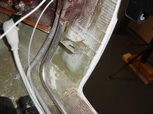
I could not used the aluminum bracket I created originally, so I had to make one of fiberglass so I could bond it to the fuselage wall. I first layed-up a 6-ply West tape with 2 additional plies at the front for the main flange. After a quick cooking and trim, the new bracket was ready to install. I carefully sanded the area for bonding. I was able to re-use the mounting strap that came with the unit - it has a buckle that allows the unit to be easily removed, but is very secure. Using two rivets to hold the bracket in place, I bonded the bracket using flox. Once cured, I re-installed the ELT and verified I could remove it for servicing. I removed the antenna from the aft compartment and re-installed it in the roll-over structure. I actually like the new arrangement better - it's in a more accessible location, is just as secure and will likely work better as there is no carbon to obstruct the signal...I just hate re-work. (sigh)
Not much to this one - it's just a 29-inch long piece of 12-AWG wire (the green one) that is attached to a short run of coax. It is simply attached to the floor of the forward fuselage with Nylon clamps that are riveted to the floor. That's it...no more to tell.
Over a decade ago, I had planned to use a handheld radio for COM #2. This was en vogue back then, as small COM radios were still very expensive and not a lot of them to choose from. Now, the MicroAir 760 is generally available, very capable and reasonable in price. Only one problem...I only installed one antenna in the winglets. In case you didn’t know, you can not use one antenna with two transmitters - unless you use a VERY expensive and very unreliable antenna relay switch. (None for me, thanks.) So, I had to install a new antenna in a winglet that was already installed on the wing. This is how Dave recommended I do it.
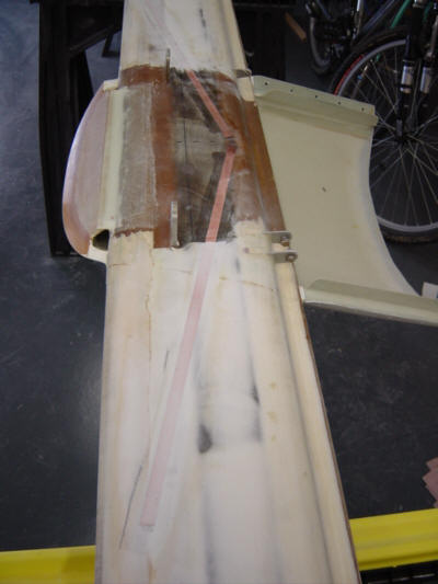
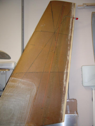
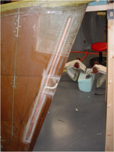
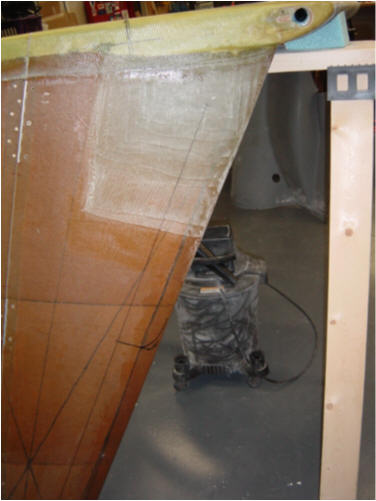
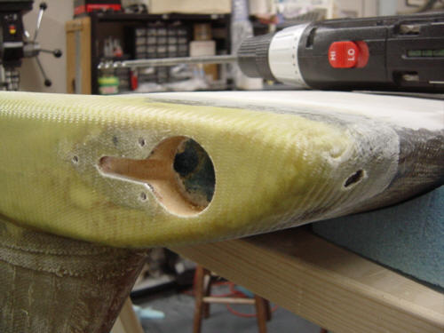
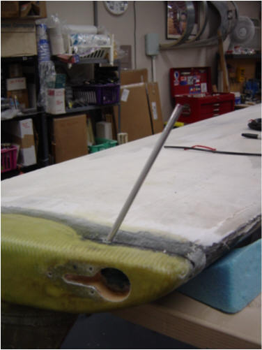
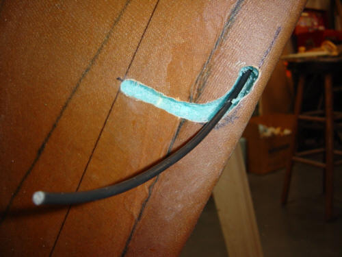
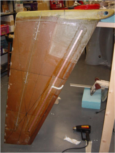
First off, I needed to map out the placement of the antenna (the wing is upside down during this operation). I dug out that copy of Jim Wier's antenna book and measured out the poles of the antenna and marked the winglet accordingly - now I have a target. Then I took a long drill bit and made a hole horizontally from the leading edge aft about 6-inches. Then drilled another starter hole in the bottom of the wing, running parallel to the inside of the winglet leading edge skin. It was drilled only deep enough to get things past the micro fill between the chunks of foam - I was careful not to drill into the internal winglet mounting structures...that would be bad. Now the fun part - I ground the end of a long metal rod to a point, chucked it into the drill and drilled down the inside of the leading edge of the winglet. Once I drilled down to the measured center of the antenna, I dug out a small trench for the coax. Taking some scrap wire, I fished around in the foam until I found the metal rod. I dug the rest of the foam out in that area and fed the coax down the new winglet conduit and then back down the main wing wire conduit.
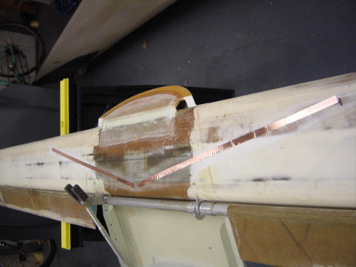
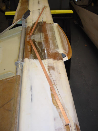
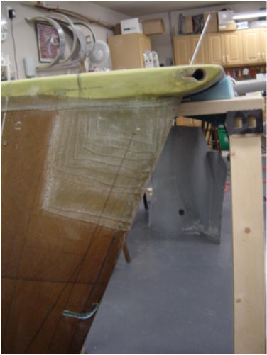
With the coax now in place, I just installed the antenna per plan. I spliced the end of the coax and added the customary three toroid beads, soldered the ends to the two di-pole copper foils. I filled the trench with micro, made the BID repair patch over it, and covered the foils with 1-ply BID for sanding protection. Covered it all with micro to be sanded at a later date...but not too much later - I gotta fly this thing soon!
This completes the antenna section. I've already tested this antenna out in the garage. Even with the metal doors shut, I was still able to clearly talk with passing aircraft. Ha! Already talking air-to-air...but I'm only 3 feet off the ground. ;-)
 Back to the Proto-page