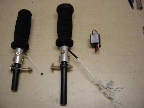
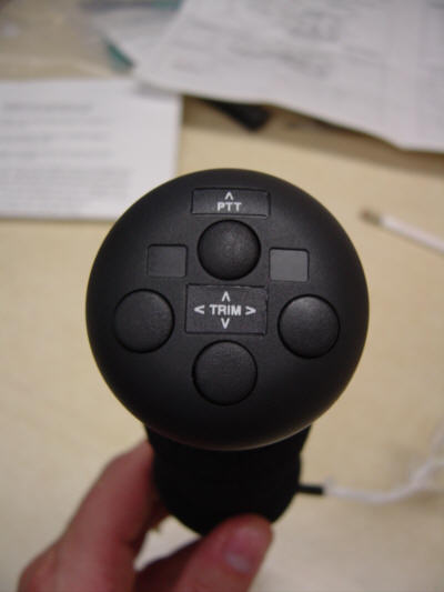
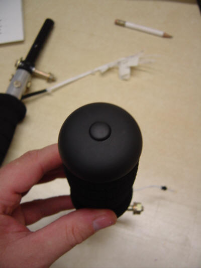
Well, you have seen the main control torque tube in the previous sections and now it's time to top them with something useful! I purchaed a set of Ray Allen Company control stick heads - one with push-to-talk (PTT) and 4-way trim for the front stick, and the one for the rear seat has PTT only. Not only did I like the look of the grips, I was also using the RAC aileron trim servo - so, it just made sense. Keep in mind that I have a different pitch trim system so I had to come up with the wiring myself. It was not hard, the instructions that came with the grip were great - in short, I give them an 'A+'.
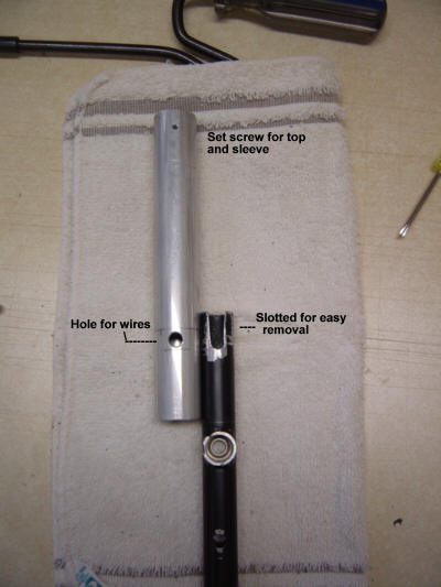
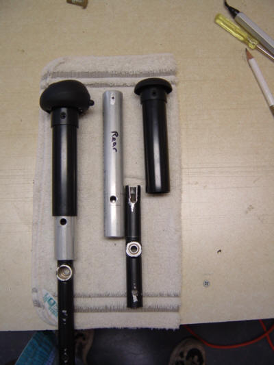
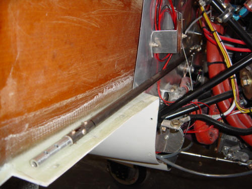
I was not in the mood for sanding one day, so I decided to start a different project to change things up. The first thing I had to do was to find and procure some 7/8-inch aluminum tube with an ID the same size as the steel pivot arms. Once procurred, I cut them down to 6-inches each, cleaned them up and started to fit them together. The second step involved drilling an access hole through both the new aluminum and the steel. As seen in this picture, I drilled a 1/4-inch hole and then slotted the steel pivot arm so that the sticks could be easily removable for maintenance...and to keep them clean for now. The upper hole was drilled and tapped for a set screw that holds the plastic sleeve and grip head on the aluminum. Here is what it looks like when it is put together - the padded grips have not been attached yet.
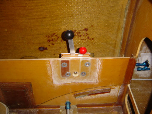
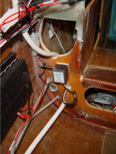
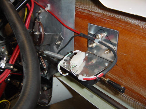
You will notice in the picture above, all the wires are labled for future hook-up and the pitch trim relay in seen at the upper right. I was concentrating so hard on the custom wiring job, I completely forgot to take and pictures - sorry. However, when it was all done and tested - I hooked them back up in the fuselage and they look great! Pictures: Front Stick and Rear Stick
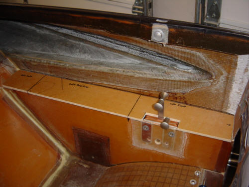
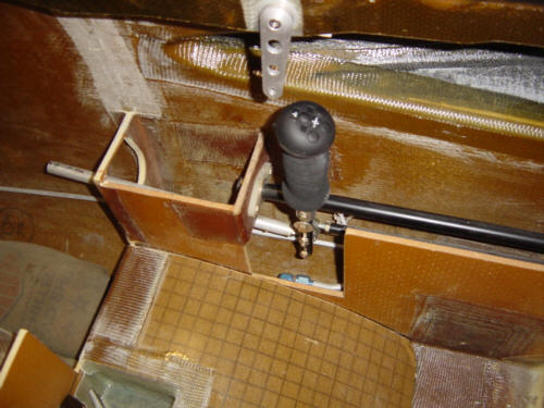
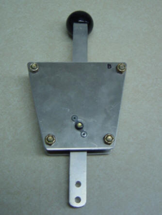
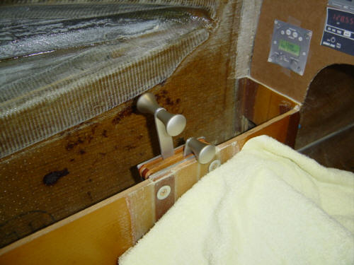
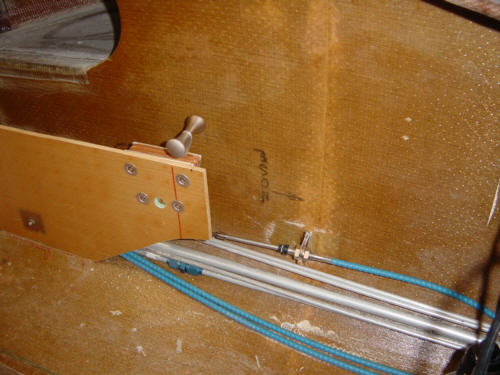
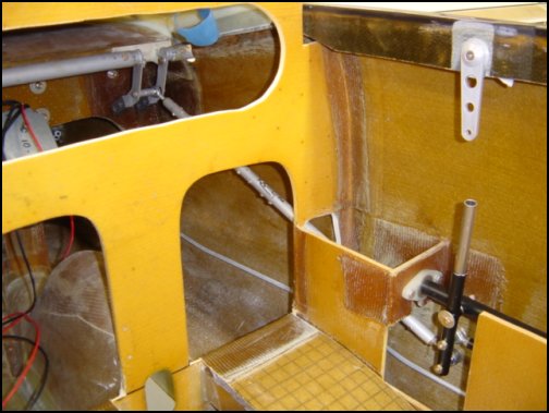
I now have another moving part!! ...a few actually. The Berkut throttles are a little different than those used by the EZs - we use the simple system sold by Aircraft Spruce. They are simple, have a good throw, and excellent feel with adjustable friction. However, we need to make a few modifications to make the install just a little better. First, the nut that attaches the center pivot bolt is replaced with an anchor nut so that friction can be adjusted more easily. In addition, all of the bolts are replaced with flush head machine screws so it can be mounted right up against the console bulkhead. 4-holes are also drilled and tapped into the front plate so the whole unit can be mounted without disassembly. The outter skin and foam is removed from the side console and phenolic blocks are installed with flox and covered with 2-ply BID glass - this is for compression strength. The throttle body is mounted with flat head screws and tinnerman washers. OK, I know what you are saying..."YUCK!" Yeah, I know, I didn't like the like the knobs that were supplied with the quadrant either. I ran across some drawer knobs at Lowes that are made of cast aluminum an have a bare-matte finish. When installed bach-to-back they from a 'T' handle and they worked GREAT! See for yourself here.
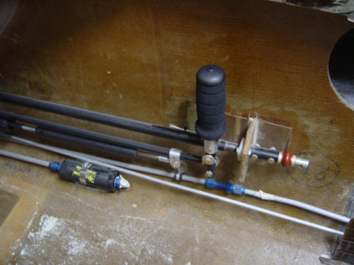
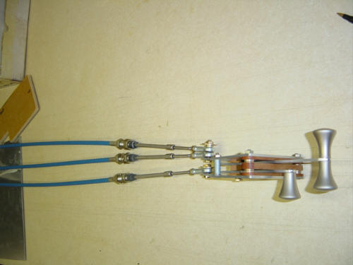
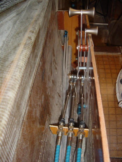
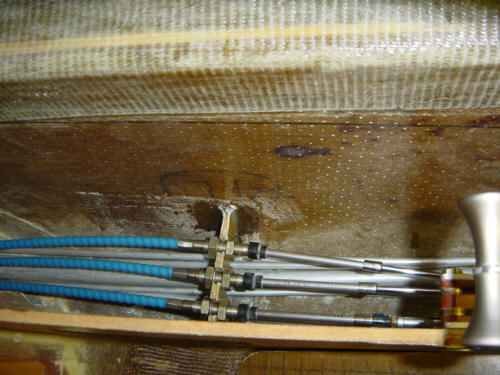
Now that the front throttle is installed, it's time to make it do something. The front throttle is responsible for 3 things: Throttle position, Mixture position, and a slave cable connection to the rear throttle lever. Those 3 cables are connected to the levers with rod ends that allow fine tuning of the travel. Of course, to function properly, something has to secure the outside case so that the inner cable has something to 'push' against. A 1/8-inch thick phenolic bulkhead is positioned between the fuselage side and the console. When properly positioned so that all the cables operate freely and are not outside a 16-degree cone of deviation, it is bonded in place with 4-ply BID tape per side. The cables clamp onto this bulkhead very well, but as an added measure of protection, the bottom of the (soon to be installed) map case floor rests on top of this bulkhead - asuring that the cables are not going anywhere. The rear throttle quadrant is also installed in the same fashion and is connected via the slave cable to the throttle lever in the front. It's always good to have a second set of controls for the GIB (Guy/Girl In Back) - the cheapest autopilot ever installed in an airplane!
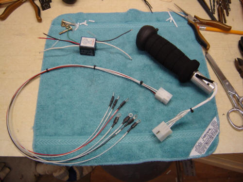
As part of wiring up the plane, it was time to hook up the control sticks for both pitch and roll trim and PTT. I used Molex connectors for both sticks, making them removable. Above pictures shows the wiring harness I made that connects to the stick connectors and runs to a terminal strip up front. Once the sticks were intalled and connected to the terminal strip, the wires for the pitch trim were run down to a set of reversing relays that convert the low amperage current from the stick switches into a larger usable current for the trim motor. Works great on the ground, I can't wait to see how it flys!
I'll do the same thing for the roll trim, but since that actuator is in the engine compartment, it will be done at a later date.
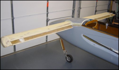
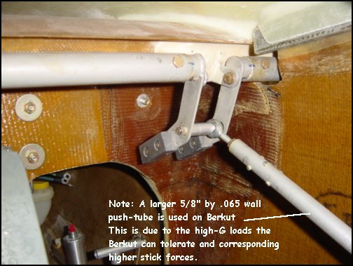
Another great day - my first functional control surface!! After the canard deck is completed, the control linkage can be setup. This is basically the same setup that the Long-EZ uses, however - take a closer look. The push-rod that connects the front stick to the elevators is substantially larger! This is one of the distinct differences in the Berkut design - because it is capable of much higher G-loads, the stick pressures can exceed that of the Long-EZ. So, Dave increased the size of the tube to 5/8 x .065 wall, from the original 1/2-inch x .035 wall. Yeah, I know...over-built - but peace-of-mind is a wonderful thing. (NOTE: Before sending comments - the rod-end is NOT in it's final position in the picture)
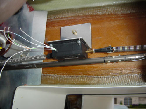
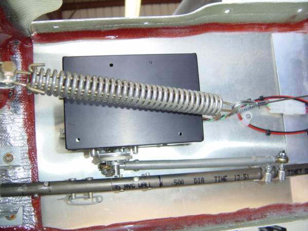
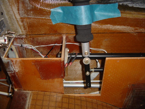
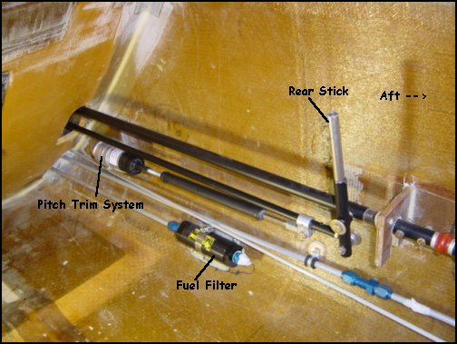
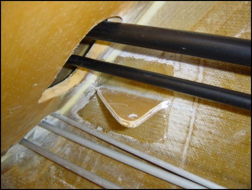
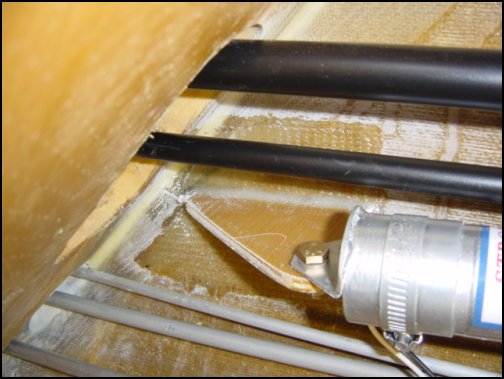
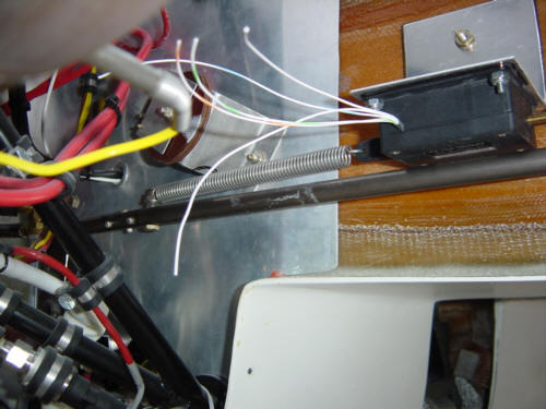
After looking around at the different units out there, I decided to install the Alex Strong Pitch Trim system. It's a nice, simple, light weight system that is currently used on several canard types with great success. It is a simple screw-drive motor attached to a tube containing opposing springs and the other end attached to the control system. As the motor turns, the spring pressure is increased in either direction for nose-up and nose-down trim. After much debate, I decided to install the actuator in the aft console compartment near the rear stick. This position allows the greatest amount of access to the whole unit, and will eventually be covered by a light-weight 2-ply BID console cover that keeps passenger feet/baggage away from the control tubes, lines and fuel filter. The actual install was very straight forward - set for neutral elevator, position unit, bond mount point to fuselage wall and attach bracket to slave-tube...that's it. Works nicely...and makes for my 3rd automated moving part on the airframe (landing brake and nose gear actuator being the other two).
I did change things up a little on the install. The original Long-EZ install shows the trim unit mounted just aft of the F10 (canard mount) bulkhead. After discussing with Dave, I choose a more accessible placement in the aft seat console. I also didn't use the heavy galvanized steel bracket that comes with the unit. I simply fashioned a bracket from 1/4-inch phenolic and attached it to the fuselage wall with flox fillets and 2-ply BID on each side. I then bolted the trim unit to the bracket loose enough so that it could pivot left and right as the control stick moves. It works great! Note that the unit is mounted low enough as not to interfere with the movement of the slave tube. And those of you who are wondering - the bracket is VERY strong and ended up lighter than the original attachment method.
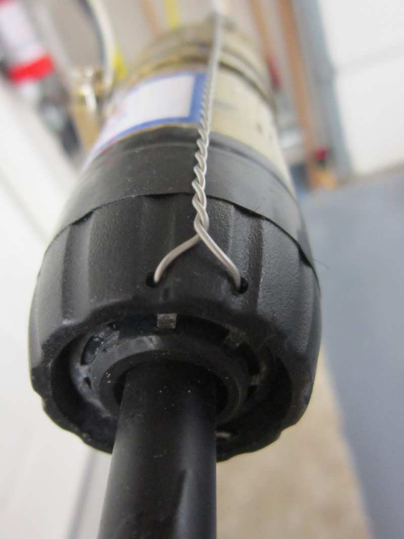
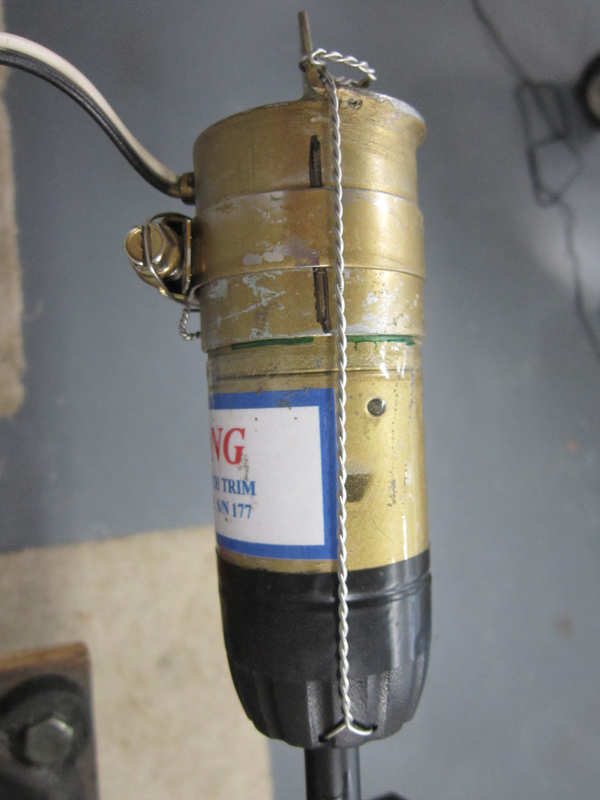
UPDATE 3-3-15: First I'd like to say, this pitch trim system has worked flawlessly for over a decade. I have installed several on client airplanes over the years that have also worked well...except this last one. I first noticed the issue when I had just finished the installation and was checking the 'max limits control movement'. I commanded full nose up trim and moved the stick full nose down...and I suddenly felt a jolt and noted the trim was no longer pulling against me - not good. Inspection revealed that the actuator motor had slipped in (but not out of) the mount. This is something you do not want to have happen in flight!! The actuator unit is held in the mount by clamp pressure/friction only in one direction. If sufficient pressure is applied to the system, it could slip and potentially slip OUT OF the mount. It would then be highly likely that the pitch controls could become obstructed by the loose actuator still attached to the pushrod and present a significant flight risk. So I devised a way to keep it from ever happening and make the system even safer.
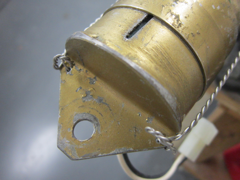
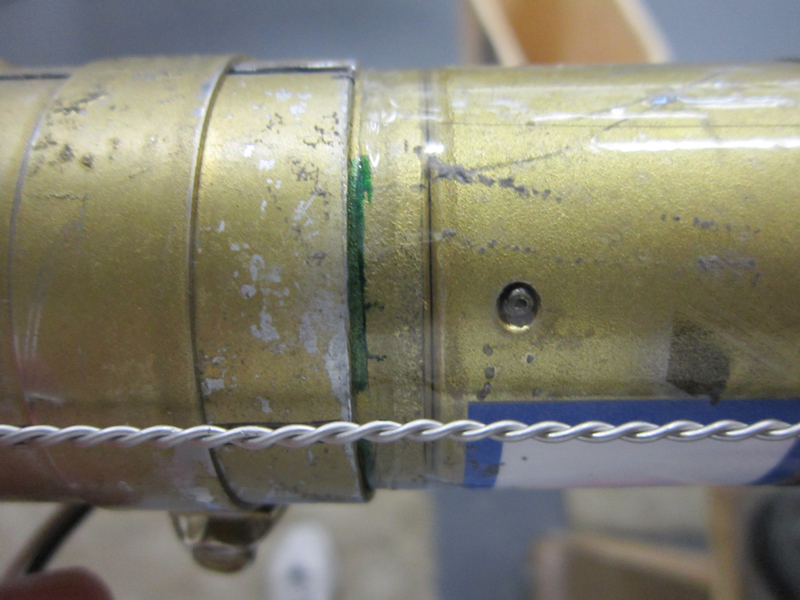
I simply drilled some holes in the clutch ring at the nose of the motor and on either side of the mount flange. Then installed .032 safety wire between the front and the rear holes to form two safety chains. I also marked the position of the mount so its stability can be checked during the annual Condition Inspection without removal. I would highly recommend that all similar systems be outfitted with the same kind of safety.
Here are a few pics of the final product: Front holes, Bracket holes, Top view, Side view, and Position mark
The linkage to the ailerons is very basic and simple. Aft of the firewall (engine compartment), we use titanium connecting rods instead of aluminum due mainly to their higher melting point. The Long-EZ folks were "urged" to replace theirs with stainless steel, but titanium is stronger, lighter, and just as resistant to heat. Hard aluminum rivets and 6061-T6 aluminum inserts are used (they are inside the TI tubes) and the 1/4" rod ends are already steel. So, a 1/2" x .035 wall titanium push rod connects the firewall control horn to the aileron bell cranks. There is also a quick disconnect insert installed on both sides so the wings can be more easily removed.
I am using the Ray Allen aileron trim servo, as are many other Berkuts out there. It's simple, compact and effective. I made an angle bracket out of some .040 aluminum scrap I had and attached the trim servo on the bottom side to be as close as possible to the push rod. The left hand spring attaches to a AN3 bolt in the push rod with a hole drilled into the end. The right hand spring is attached to the push rod to bell crank attachment bolt, also with a hole drilled in the end (not shown). The positioning allows the springs to always be in tension regardless of the push rod or servo travel - assuring that the springs can not come off or bind. So, after wiring it all up, I tried it out and it worked perfectly. It even registers correctly on the ACS2002 trim display. I love it when things actually work!
OK, so I have some time on my hands before 1st flights (I'm waiting for the transponder to come back from "down-under"), so I'm trying to get a few things completed in the mean time. One of those thing is the autopilot servo. I had run the wires, and installed the main gyro-head back when I was setting up the panel and running wires - so all that remained was the physical installation of the servo. I invited a few of my Long-EZ buddies Ron Gowan and Doug Bryan to help. I was a simple job, but I wanted the company and needed to be in two places at the same time! It worked out perfectly - I was inside the plane with my arm painfully inserted into the main spar, Doug was drilling and helping guide the bolts, and Ron was supervisor. ;-) Actually, it was a tag-team of all of it. Anyway, with only about 40% of my tools out at the hangar now, I was ill-equipped for this install and had to also enlist the aid of fellow EAA'ers on the field. (Thanks, Tom!) In all, the bolts are in, the push rod is assembled, and the servo is centered and working properly. I have an autopilot! And to think, I was not even planning on having that installed for several more weeks. Thanks guys!
 Back to the Proto-page