UPDATE 4-22-04: The Hydraulic system is COMPETE and tested! That's right, I have fully functioning landing gear!! This is almost as kewl as the engine start.
Doug Bryan, a Long-EZ buddy of mine, came over to help out this evening and was immediately put to work. (Thanks again, Doug) The night before I had tightened up all the fittings, and rigged up a little extra aluminum tubing to dump the lines into containers on the floor. The first thing Doug and I did was to load up the pump with hydraulic fluid and ran 2 quarts through the high pressure lines and bled them out into waste cans. This was to flush out any contaminants from the system. After disconnecting the bleed tubes and hooking the lines back up to the gear door cylinders, we did the same thing with the low pressure side. Now, with the lines bled, and flushed out - it was time for the "big swing"!
The sequence valves, now fully pressurized, needed to be adjusted a little bit...but after a quick turn of a screw and a slight bend in the valve's lever - everything was a go! Words just don't do it justice...here are a couple of movies to show you what it was like:
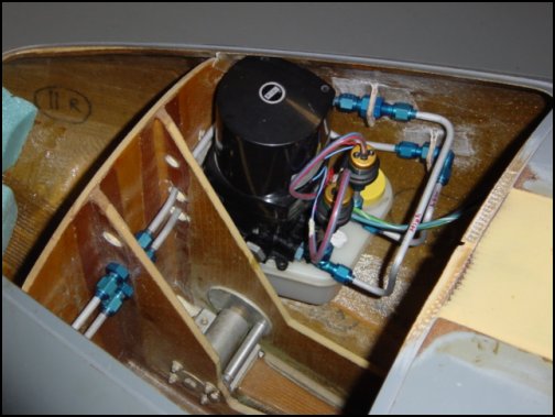
This is a short section, but represents alot of work hours - bending tube, screwing up tube, and bending again. Dave tells us builders to order DOUBLE the required amount of tubing and that would be a good start. Now that the nose gear is no longer going to be hydraulic, I have totally re-worked the front system. I have upgraded the aft section too. I have replaced the oringinal 'el cheap-o' cylinders with the good ones, and have upgraded the original 303-type hose with stainless-braided teflon. Whew...that was a pain too! I can't tell you how many fingers I bloodied with the frayed ends of the hose while ataching the fittings.
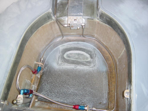
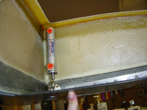
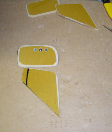
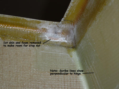
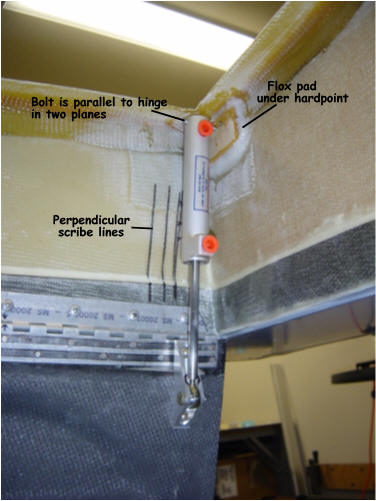
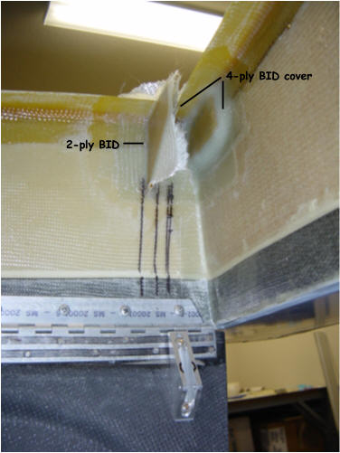
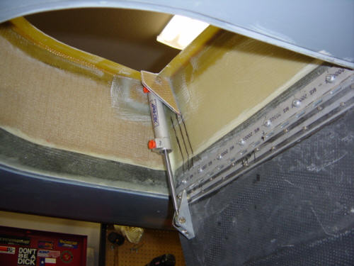
This was a rather tedious process with all the setup, measuring, alignment, and cramped spaces - but, I'm happy with how it turned out. The outer gear doors are hydraulically actuated and also serve as the up-locks for the gear legs. The install starts by attaching a aluminum bracket to the gear doors. It was important to make sure that the bracket is installed perpendicular to the hinge line. If any of the following items are not aligned properly, the geometry will be off and the cylinder will bind. Once the bracket is re-attached to the strake, a trial fit is done. With the cylinder in its position, a series of measurements and scribe lines are made. This will establish the mounting position of cylinder and the placement of the hardpoints. A nut plate is riveted to the back of the phenolic hardpoint to the bolt can be retained. Reference lines are drawn on the strake rib and some skin and foam are removed to make room for the nutplate. The head is cut off of a old bolt so that when the hardpoint is floxed into position the alignment can be checked and re-checked until the flox is semi-cured. A second bracket is installed to keep the bolt stable and BID covers are added to the whole area. When cured, the mounts are cleaned up and the cylinder is tested for binding. I had no binding at all so I didn't have to modify or change anything! A couple mounting tabs and fittings are added in preparation for the 1/8-inch feeder lines, sequence valve, and flex lines. And, as you can see above - the finished product.
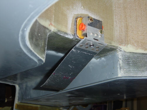
The sequence valves allow the high-pressure charge from the hydraulic pump to flow to the other gear door cylinders at the correct time. As the gear leg is retracted into the gear well, the leg depresses the 'flapper' tab that in turn activated the valve. The gear doors then follow the gear leg as it folds up into the gear well and then act as the up-lock for the gear. Of course, the same thing happens in reverse order when the gear comes down. This may be a bit hard to imagine, but I plan to put a few movies of the gear system in operation once testing is complete - that should help.
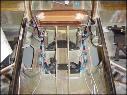
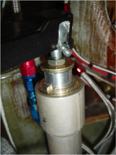
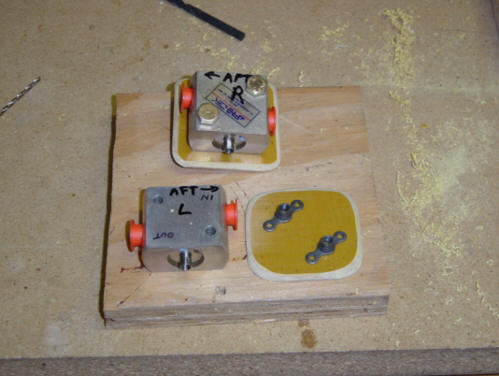
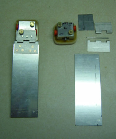
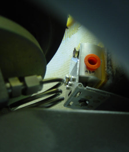
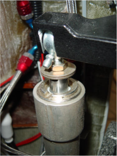
Installing them was really easy. First, I has to make a couple phenolic mounting plates that will be bonded to the inside of the gear well. There are a couple of nut-plates riveted on the back that the bolts are screwed into. Once those are completed, wet flox is used to bond them on the inboard face of the gear well. A couple of bolts that have been waxed are installed to make sure the flox does not fillup the nutplates and threads. While that is curing, the flapper arm is attached to the sequence valve with a piece of aluminum extension, a small section of piano hinge, and a 6-inch long piece of .050 aluminum sheet. There is a small screw that fits through a hole in the hinge and allows the flapper to swing up and down and activate the valve. Completed and installed, it will look like this from below. Note how little space there is between the brake line service loops on the retracted gear leg and the bode of the valve. I actually had to go back and re-do my brakes lines to make the loop smaller. I still need to do a little clean-up work here - fair the mounting plate, add the stainless lines to the gear cylinder and the main system, test and adjust. But most of that work will come once the plane is inverted for easier access.
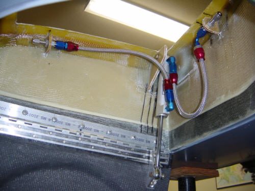
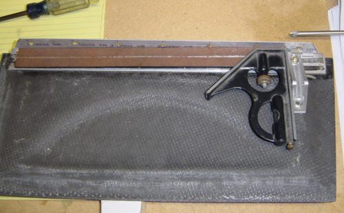
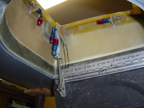
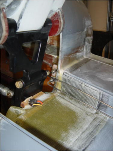
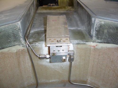
During the bottom finishing while the plane was on its back, I took the opportunity to install the hard lines for the main gear doors. These lines are 1/8-inch stainless steel and are connected to stainless steel Swagelok fittings. The reduction is tube size, from the 1/4-inch internal tubing, compensates for the smaller size of the gear door actuator and slows its retraction rate. This gives the gear a smoother and more positive up-lock.
The lines run from the high and low pressure fittings inside the fuselage, along the gear leg depression and feed into the gear well and the sequence valve. I had to make a fitting change on the valve - the original plans called for two 90-degree fittings, but I found that the fitting facing the gear leg did not have enough room for a 90-bend. Swagelok does not carry a 45-degree fitting of this type as a standard, so I opted for a straight fitting and changed the tube bends. Problem solved.
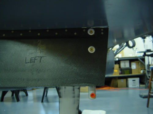
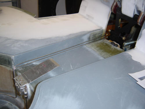
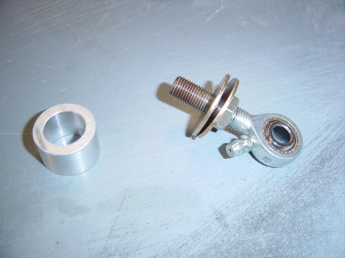
The travel of the main gear hydraulic arms are just slightly longer than the travel required to articulate the gear - so a little adjustment is required. First the rod-end is adjusted at maximum arm extension as the gear is fully retracted - this sets the "fully extended" geometry. Then the gear is extended and the amount of remaining travel is measured. Then an aluminum collar is machined to length and two large area washers are added to the rod-end. These washers act as the stopping surface for the hydraulic arm as it retracts onto the sleeve. Before the sleeve is installed, you can see here the remaining travel that will be reduced by the sleeve. All together it looks like this. That's it for the aft section...all I have left now is to test and adjust the gear!
 Back to the Proto-page