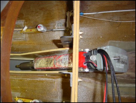
Here is another retro-fit modification to my aircraft. The original hydraulic nose gear system only allowed the nose gear to be moved in flight - it could never lift the nose off the ground. This also meant that an isolation valve had to be manually moved, and the main gear pump engaged to retract the nose gear for parking. Now with the new actuator installed, the nose can be raised and lowered on the ground = making it MUCH easier to get into and out of the plane.
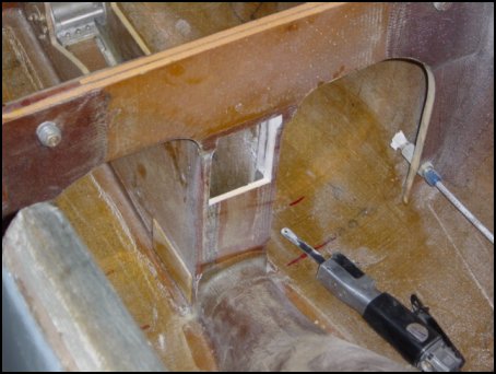
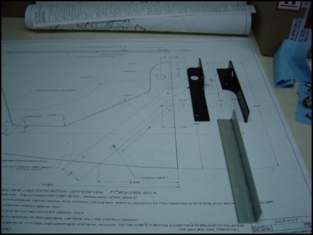
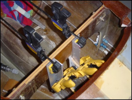
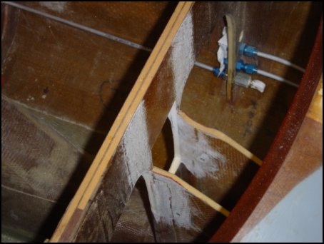
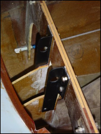
First, the old system is completely removed and a hole is cut in the F10 bulkhead to allow the longer body of the actuator through. Since this material was removed, and this is a retrofit, it is necessary to fashion some brackets to spread the increased loads onto the F10 bulkhead. The brackets also utilize the same hardpoints as the original hyd. system for easier installation. Aluminum extrusion is used positioned on the intersection of the F10 bulkhead and the NG-30 stringers. The holes are back drilled and the excess extrusion material is removed. The brackets are primed and painted for protection are ready to be installed. They area is prepared and the brackets are bonded and bolted into place. Large area washers are used on the aft side of the F10 for additional strength.
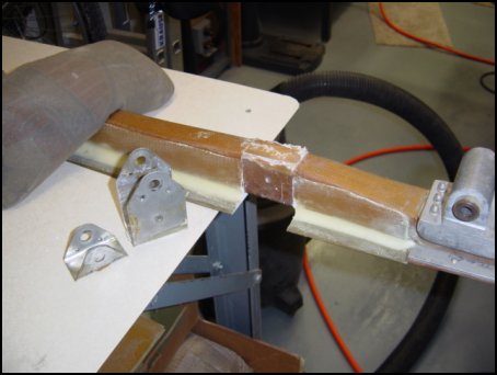
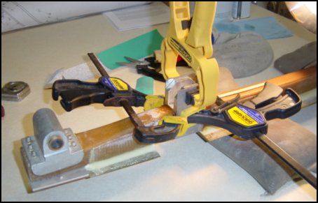
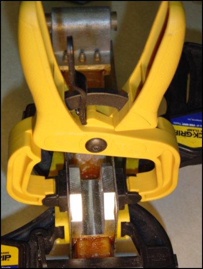
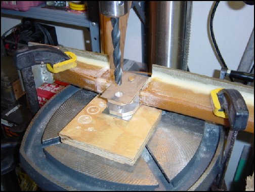
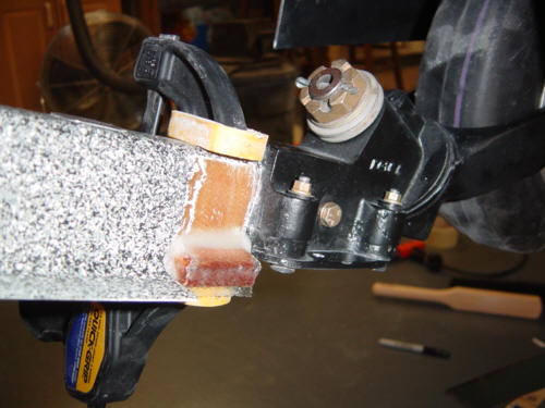
Of course, this also means modifying the nose gear strut. The old attach bracket is removed so that a high-strength bracket can be installed. You can easily notice how much thicker the bracket is. This is to accommodate the increased loads of raising the lowering the nose of the airplane fully loaded. Once bonded, a hole is stepped up to final size of 1/2-inch on the drill press. Finally, the whole assembly is cleaned up and reinstalled in the nose.
UPDATE: 10-6-02 - Nose Gear Actuator Testing
MPEG Movies: Nose Gear Down (1.2mb); Nose Gear Up (1.3mb).
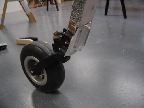
UPDATE: 5-26-03 - Replacement Nose Gear Tire
The original tire seen in all the previous pictures is gone - I just replaced it with new no-tread tire that most of the Long-EZ drivers are already using. You see, when taxing, the tread on the old tire picked up little rocks and launched them into the prop - causing nicks and chips. The theory here is that without tread, the amount of debris picked up will be reduced dramatically. Besides, there is no reason for this tire to have a grooved tread in the first place. A second benefit is that the old tire was constructed poorly and was out-of-round - the new tire is very well made.
UPDATE: 6-4-03 - Nose Gear Doors
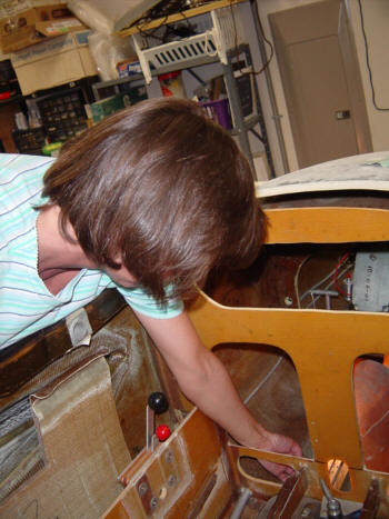
I also installed the nose gear doors. I had cut and attached the hinges to the doors many years ago - they are both bonded and riveted just like the main gear doors. Sandy helped by positioning and holding the nut plates as I drilled and mounted them with Cherry pop rivets. The final product looks something like this. Once the doors are one, a simple retraction spring and wire loop are installed and attached to the doors. As the gear leg raises, it catches the center of the spring and pulls the doors up into the closed position. The wire keeps the two doors in sync and holds them open when the gear is extended. Here is a picture of what it looks like installed (looking forward).
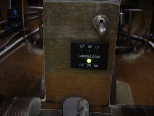
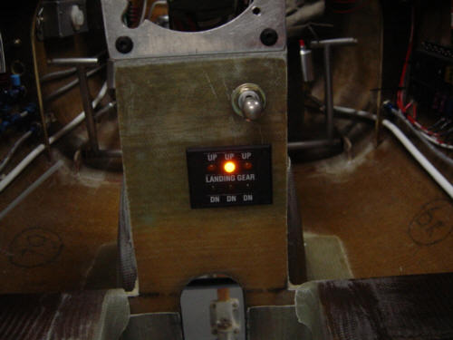
UPDATE: 11-19-03 - Nose Gear Position Lights
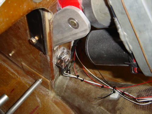
As part of the wiring in the front of the plane, I installed the circuits that supply the gear status lights. The actuator relays are self contained, so wiring was easy - hook up power, ground and connect to the gear switch. The status lights were another matter. Clayton's actuator had it's own green LED to show down and locked and I wanted to hook into the Ray Allen lights. No problem! I used a microswitch for the up sensor and a little relay to convert a +12v signal into a ground fault to activate the lights. So, now I have a nose gear status of: Green = down and locked, Yellow = in transit/unsafe and no light at all means up and power off.
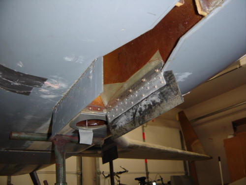
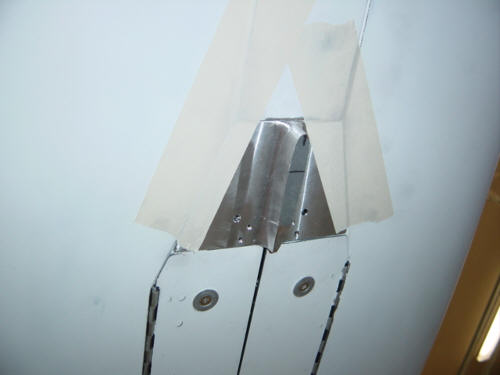
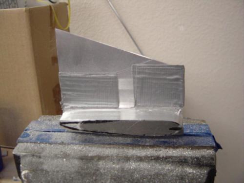
I've been meaning to plug the hole in the front gear for a number of months now...so I finally did. I installed the aluminum nose gear "foot" so that the fairing on the strut doesn’t hit the ground when the nose is lowered and raised. The geometry is a little funky when the gear is just about to close the gear doors...so a little extension is used as a "foot" during that portion of retraction/extension. Other times, it is just drag producer...so we take some pains to minimize the frontal area and make an airfoil shape to keep the airflow attached.
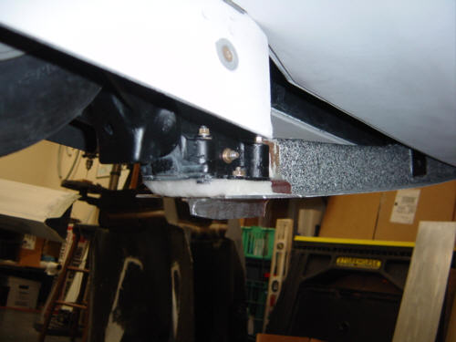
So, the first thing I did is cut the aluminum to fit the gear well depression - this forms a trapezoid shape. Then I removed it to file and grind the tab into an airfoil shape to minimize drag. To mount this to the nose gear strut, I had to make a forward mounting bracket. I simply took a thick piece of phenolic and floxed it to the strut and covered with 2-ply BID. After cure, I drilled and tapped to holes through the foot's plate and into the phenolic and the retaining plate on the nose wheel assembly. I then used a pad of flox between the two and extended it to the rear to help smoothly guide the gear doors closed. The mounted foot looks like this. Since this was a retrofit, I'll have to go back and Zolatone and paint the foot - Oh well...I'll do that in-between some other process.
In case you didn't get enough, here are a few more movies of the foot in action:
Nose Gear coming down 830Kb file
Nose Gear going up 668Kb file
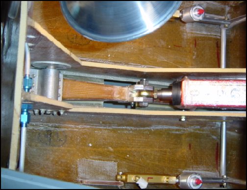
The final item that is completed in the "B" kit is the nose gear. The nose gear strut connects to a smaller forward bulkhead and the F10 bulkhead for the canard. In the picture above, you can see the two NG-30 stringers, the forward bulkhead, the strut and the hydraulic cyl. Also seen in this picture is the hydraulic pump itself - mounted on the aft side of the forward bulkhead.
This smaller gear installation acts as practice for the more difficult main gear installation in Kit "C". Not shown in this picture is the nose gear caster, wheel and tire. That assembly can be seen in many of the future pictures.
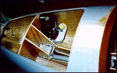
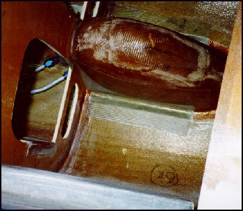
This is a picture of the installed nose gear bowl that houses the retracted wheel and strut. It is mounted between the F10 canard bulkhead and the instrument panel. There is even a small window of the lower instrument panel to provide a visual check for positive gear retraction/extension. Notice the bottom sides are flat and have addtional plys. These were constructed to accommodate the piano hinge for the front gear door. These doors will be installed at a later date.
 Back to the Proto-page