Well...time to work again with my old adversary again - metal. I hate the stuff, but I have to use it here - it's the best material for the job. So, I went out and bought $125 worth of various thicknesses of 6061-T4 aluminum and promptly took it directly to a local aircraft repair shop along with the baffle drawings. (I'm not too proud to admit that I want someone else to cut out and brake-bend these things!) I walked in, un-rolled the plans and asked "Can you take this aluminum sheet and turn it into these?" (pointing at the drawings) The guy looked straight back and said, "You bet we can." I responded, "Deal!" ...didn't even ask about price. They were very fair, did a great job and let me tell you...it was worth every penny. So, I now have the cut-out parts with most of the difficult 90-degree brake-bends completed. I would still have to bend several things to fit the engine and cut all the final trim areas. Which brings me to the first thing I had to do...bend the inner baffles:"
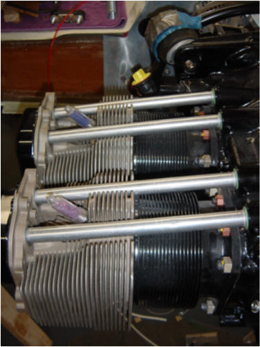
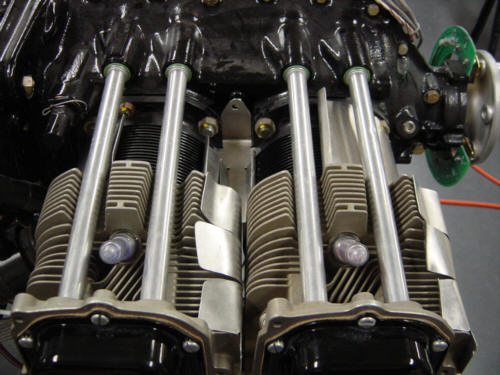
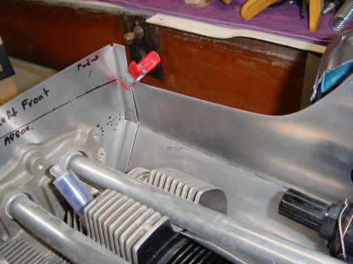
The first things I shaped are all the inner cylinder baffles - shown here after being bent to fit the engine cylinder barrels and cooling fins. These baffles direct cooling air around the inboard and the exhaust side outer fins of each cylinder of the engine. If these baffles were not in place, the air that is scooped into the lower cowling would easily slip around the cylinder fins through gaps and holes and not cool things efficiently. The baffles not only block the gaps, they force the air to circulate around the entire barrel of fins and maximize the cooling effect.
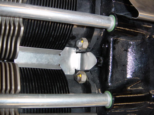
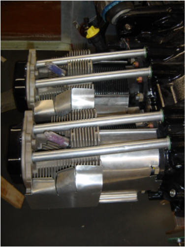
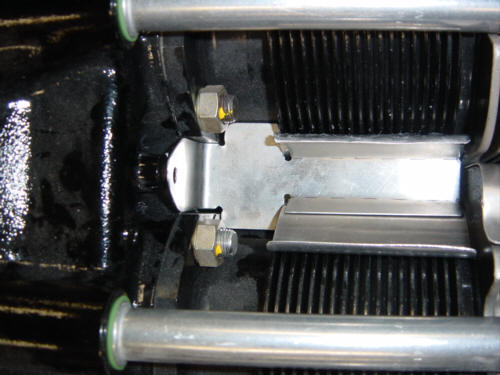
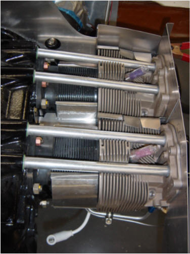
One of the biggest gaps is between the two cylinders on each side of the engine. This center baffle is designed to plug that gap and help hold the inboard baffles in place. Next, the outer exhaust side baffles are form fitted to the cooling fins on the cylinders. I used cylinder #1 to form all of the parts since they are all the same shape, and #1 was the easiest to access. Also shown in that last picture is the left, aft, inboard baffle. It’s a little bigger than the others since it will also form the aft wall of the larger engine compartment baffles - more on those later. After a few trial fits I was ready to bond the cylinder baffles onto the fins. Attachment is simple - just put some Clear RTV Silicone on the baffle, smooth it out into a thin film, and stick it on the cylinder. In this shot, you can see how the center baffle is used and how the sets of inboard baffles are configured. Looking at the underside of the cylinders you can see the larger gaps between the "C" shaped inboard baffles - this is designed to scoop the air in from below and force it out smaller openings in the top. Once all of the inner baffles are siliconed in place, they look like this.
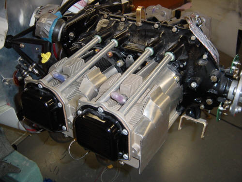
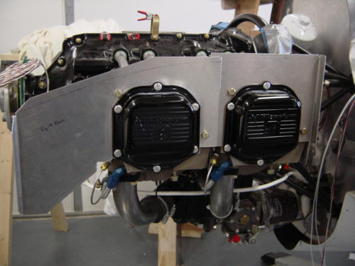
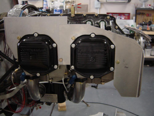
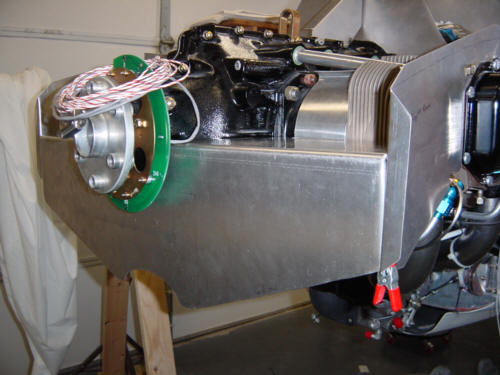
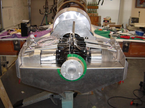
Now that the inner baffles are complete, it is time to concentrate on creating a compartment surrounding the engine that directs the airflow. So, the first items to be installed are the side baffles. These consist of 4-seperate plates that are installed directly onto the cylinder jugs on both the right and left sides. The plates will remain separate so that the cylinders can vibrate independently without causing cracks in the baffles. These side plates also provide support for the fore and aft baffles that complete the engine compartment. The forward baffle plate is shaped to fit the engine case and is installed at the top-forward portion of the engine. It is supported by a center stiffener that is attached to the engine centerline. It also connects to (and is bent to match) the left side and right side baffle plates too. It's all clamped into position now but will be permanently riveted together and trimmed down to exact cowl fit at a future date.
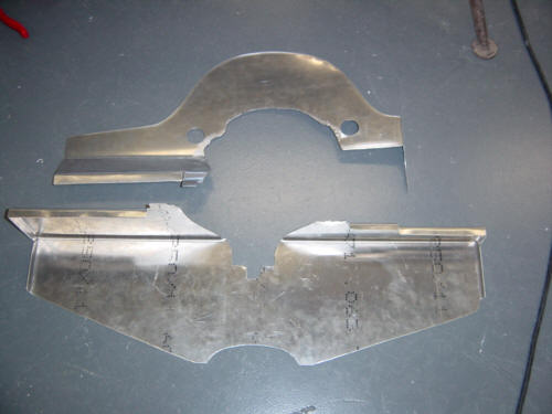
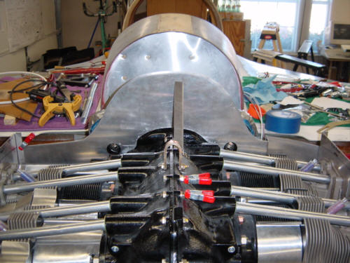
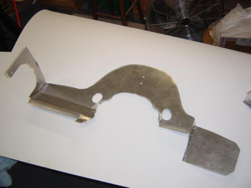
The aft baffle was a very difficult animal to tame. It has multiple bends, intersections, and attach points that made it rather difficult to trim to fit. But, after several trials, I finally got it all to line up. It serves as the final barrier for the scooped air in the cowl and separated the upper and lower airflow. You can see here how it fits into the underside of the engine now. I will also have to cut out holes in the after baffle for the alternator and starter to stick through. But for now, this is what it looks like but still needs to be trimmed to exactly match the cowls.
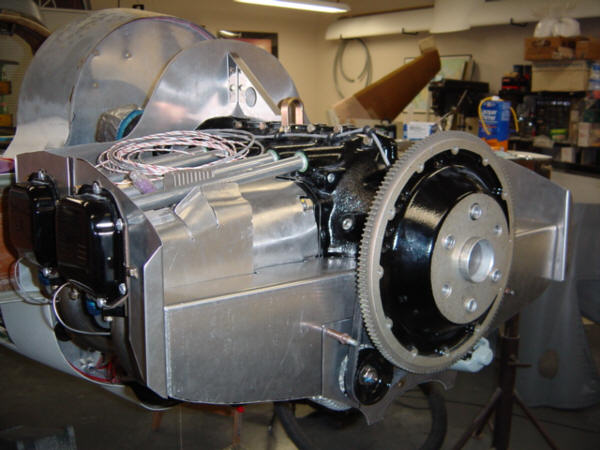
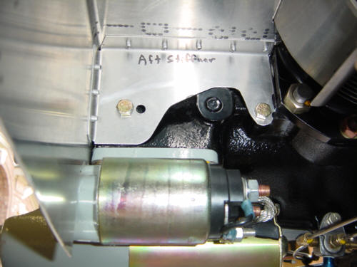
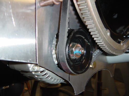
UPDATE 2-23-04: CRAP!! I just THOUGHT it was time to trim stuff up. I tried putting the flywheel back on and...tang...it hit the aft baffle. Grrrr! The whole thing needs to be moved a full 9/16" further forward. (sigh) After another day "put on, take off, trim, repeat"...I finally managed to get the aft baffle in the correct spot. You can see the old holes in the aft baffle stiffener. Oh well, no one will see them...oops, too late.
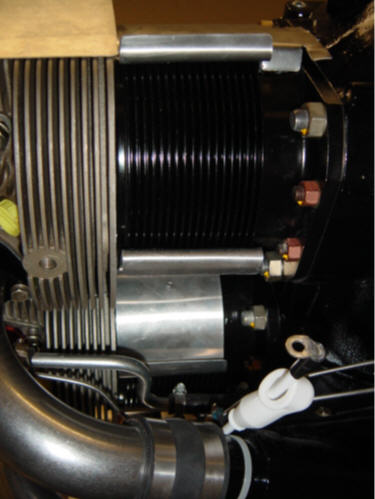
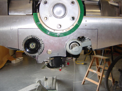
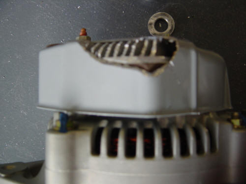
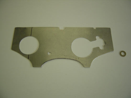
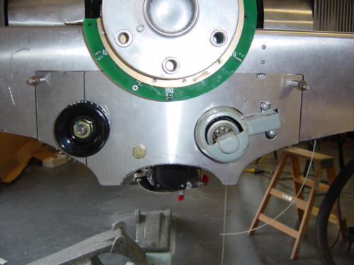
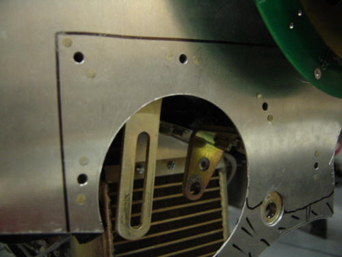
Finally, it was NOW time to trim up the baffles, and install the engine accessory holes. I started out by rough-cutting the alternator and starter holes out larger than required. I also had to make some additional cut-outs to expose one of the starter studs so I could actually get the nut on it. Not to worry, there will be a doubler plate created to close the gaps up in this area. Since I have an all-electric airplane (including cabin heat), I am using a slightly larger 60-amp main alternator from B&C. To make it possible to install the drive belt, I needed to cut away a little bit of the diode heat sink and case to increase the clearance to the engine block. This little mod is being used by several other Berkut'ers and yields about 1" of adjustment room. It also allows the alternator to mount very closely to the engine block there-by minimizing the blister on the cowl. Good stuff!
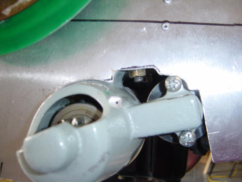
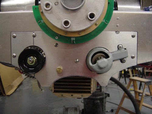
After another tedious process of "trial and measurement", I cut-out and created the doubler cover plate. It cleans up the whole area and reduces the clearance around the accessories. I have it cleco'ed in place in this picture, but I'll install nut-plates and bolts to mount it permanently. You will note, that there is still enough room to adjust the alternator even with the doubler in place. It also has some extra room around the alternator to allow for proper cooling. I also riveted the sub-parts to the forward baffle to finish it off for final attachment. With that...the baffles are now complete. I'll come back and install the border seals later.
UPDATE 3-7-04: I did a little clean-up work in on the doubler plate tonight. The original plans just say to rivet it on to the aft baffle, but I wanted to mount the doubler plate so that it could be removed for servicing the alternator and starter. I can't imagine having to drillout all those rivets just to pull an accessory. So, I attached a few nut plates with flat head rivets to the forward side of the aft baffle. This not allows for several stainless steel screws to mount the doubler. The nut plates are the locking variety and positively hold the screw in place. Mission accomplished.
 Back to the Proto-page