
OK, folks....there is no mistaking that the one construction process I actually feared doing...is now under way. This is one of the more critical sequences in the whole airframe as the alignment, balance, and even the gaps will directly dictate the smoothness (or lack) of the control system. One of other reasons that I'm a little shaky is that this section of the plans was never really completed, and no one else has reviewed, corrected, or proven the information correct....yet (in fact, the existing plans had some MAJOR GROSS errors...more on that later). Most, but not all, of the planes flying today were constructed by or with help from professional builders - including Dave himself - so there has not been that much pressure to complete them. Now, even with the company not producing kits anymore, Dave has still been providing builder support when he can, and he has been "holding our hands" through this process - so I'm not completely without a safety net. In addition, Ric and Shari Lee (Berkut 540 builders in UT) with input from Dave, myself, and other builders are taking on the additional challenge of completing the plans as we build our birds so that others will not have the challenges we did. With that said...lets move on to building.
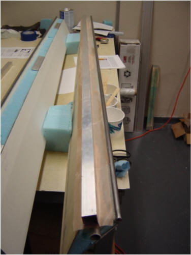
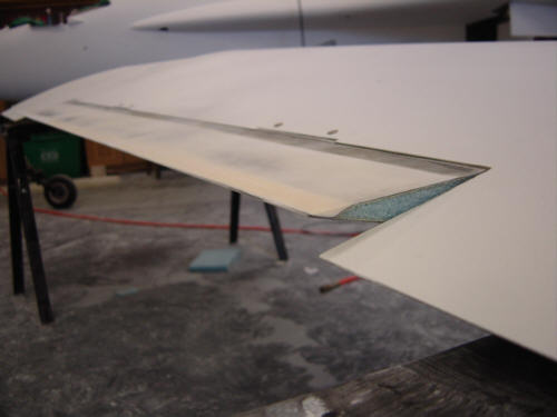
Step one: cutting out the aileron cores. OK, this was the scary part...remember, one mistake here and you are building new wings! ...and that actually almost happened to me!!! (not a joke) The Berkut ailerons are longer and wider in cord than the Long-EZ specs, but basically they are constructed the same way. First, you draw out the dimensions of the aileron on the wing and cut them out. Simple enough, huh...WRONG! Let me now tell you the scary story: Remember the "gross errors" I mentioned above...here is one of them. I had followed the plans exactly as written and had drawn out both the top and bottom aileron dimensions on the wings - I measured, checked, measured, checked and verified again. I was JUST (and I mean saw blade in hand and lined up) about the poke the saw into the wing...and stopped (divine intervention is my only guess as to why!). I looked up at the Berkut picture on the wall on the garage, and just noticed that "something didn't look right". It just seemed that the aileron surface was kinda big. So, I measured again...all was still physically correct...but still "looked wrong". Given my paranoid approach to this section, I looked over the Long-EZ plans and templates and discovered that the Berkut plans I was using had the upper and lower surface dimensions TRANSPOSED! (the two measurements are very different in chord) A simple mistake on paper could have destroyed my wings - literally!! Yep, I caught that mistake JUST SECONDS from ultimate, un-recoverable disaster. A mistake of that nature could not have been repairable in any way - might as well have taken a chain saw to them. I called Dave, re-confirmed my findings, re-drew the CORRECTED dimensions, and spent at least 20 minutes laying on the floor thanking God for his help and trying to stop shaking. I can't express in words the spectrum of emotions I went through...but I can tell you this - I'm thankful it's behind me!
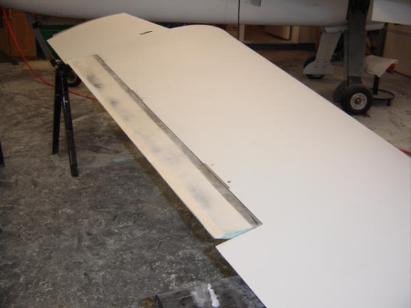
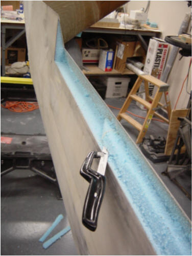
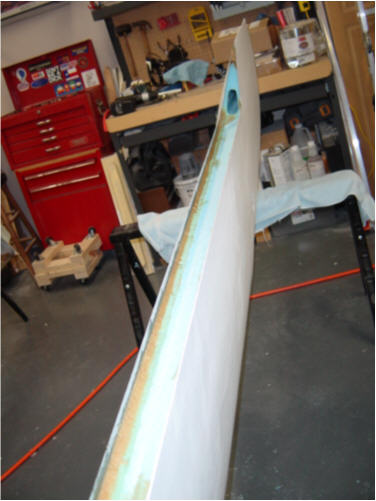
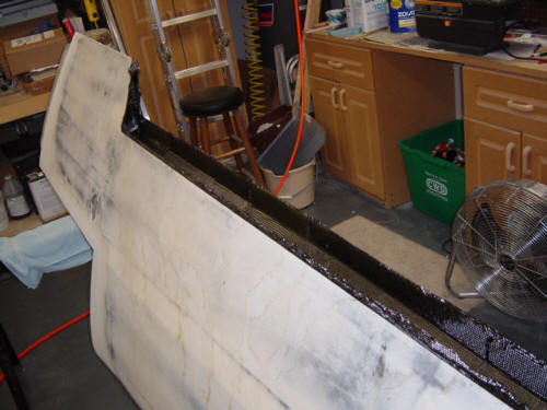
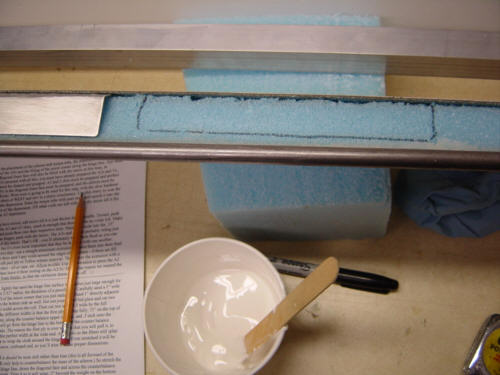
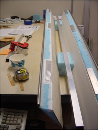
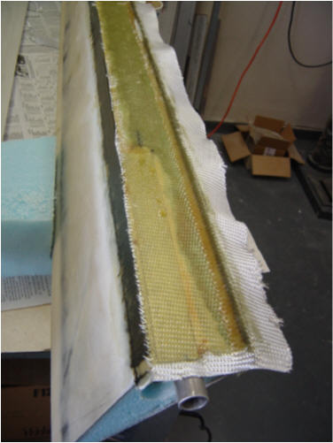
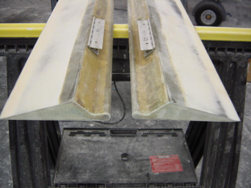
After I collected my wits...I actually cut out the ailerons. I used a straight edge and a hack-saw blade to cut into the skin first, then went back at an angle to cut through the foam. The flexible blade of the saw and the angle at which they are cut made for a few minor deviations in the foam. No problem - this foam gets removed as the next step is to clean-up and remove the foam in the aileron channel so that a false spar close-out can be put in. 11-years ago, when I built the wings, I laid down strips of peel-ply under the carbon wing skin where the aileron cut-outs will go. It was now finally time to remove the peel-ply to expose the bare carbon under it. It literally took 4 hours to remove all the peel-ply as it has been buried in the wing for SO long. It is really designed to be removed within a few days of the original lay-up. Oh well...it was difficult but all turned out fine. The remaining foam in the channel is sanded at angles to make a trough to lay-up the closeout and hinge mount pads.
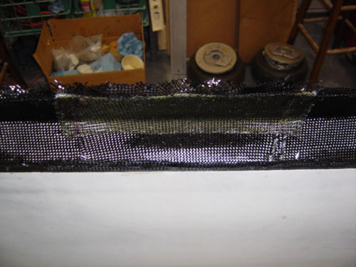
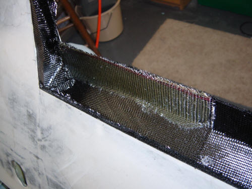
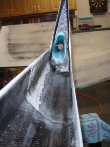
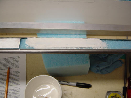
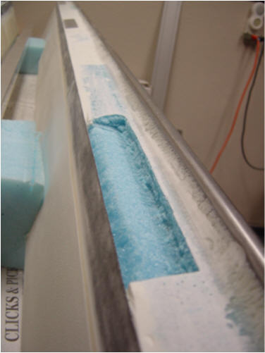
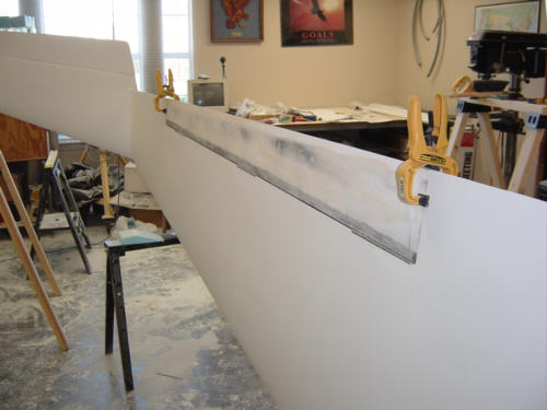
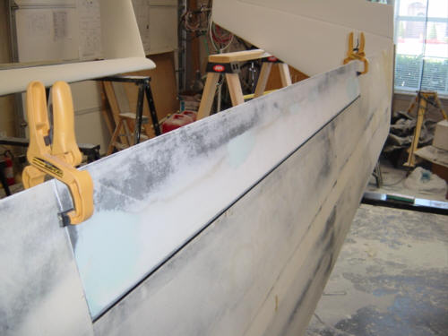
Now, another departure from the Long-EZ construction is the use of carbon fiber in the channel. The larger Berkut ailerons and stiffer wings significantly increase the roll rate of the plane...and thus more force is applied in this area and it needs to be stiffer to handle it. The process is rather straight forward starting my applying EZ-Poxy flox around the corners of the wing skin and foam. Then 5-plys of BID carbon fiber are laid-up to full length in the channel. 2 additional smaller plys of carbon BID are placed where at the hinges will be attached to form mounting pads. As you may remember, carbon fiber and metal do not mix and you will notice there is also a single layer of BID glass added to act as insulation between the carbon and all the hinges. The ends of the cannel are also capped with 2-ply of carbon BID. Once cured, the extra carbon will be trimmed back to the original cut-lines and the cannel will be ready to receive the completed ailerons. It was difficult working in such a small area, but a little added heat got the job done nicely.
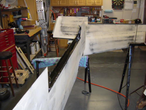
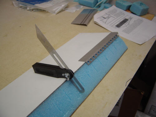
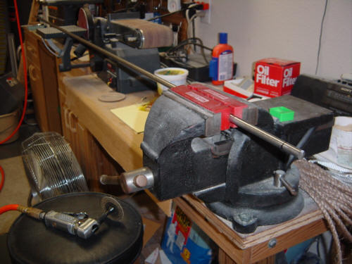
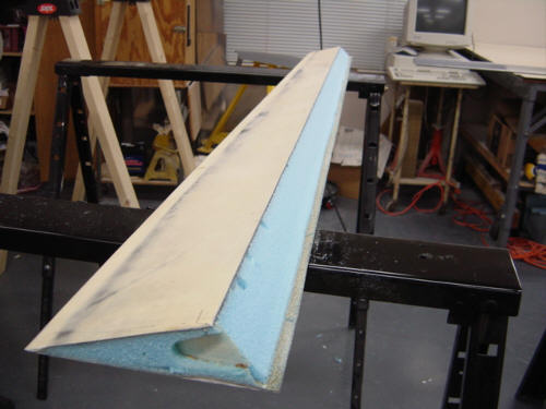
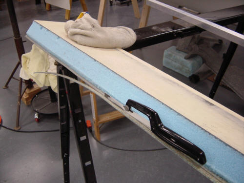
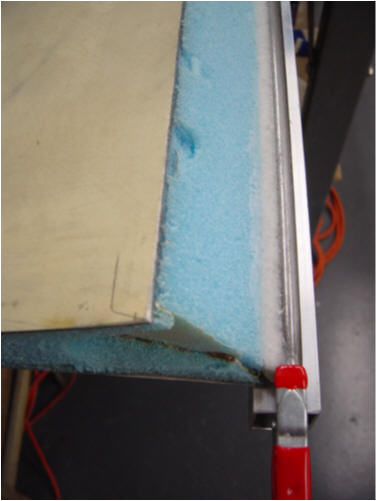
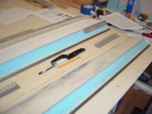
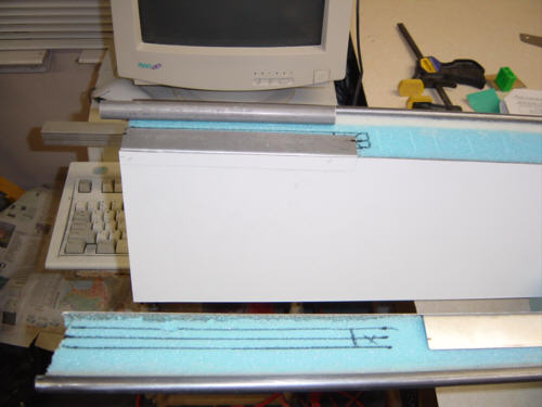
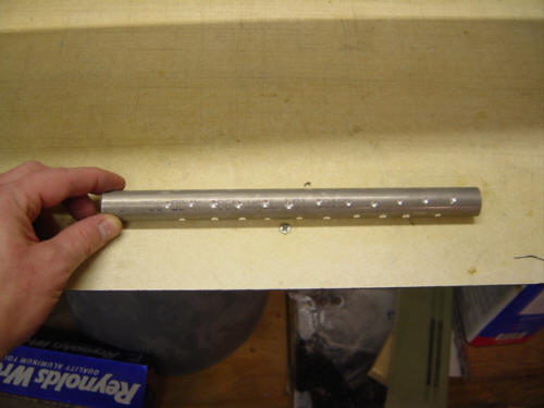
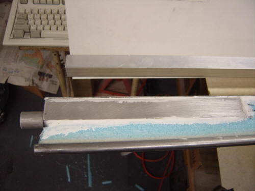
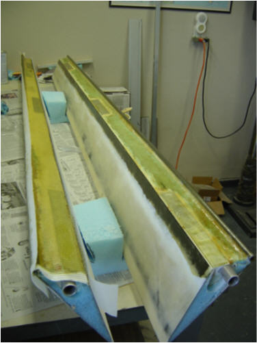
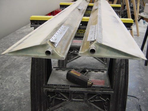
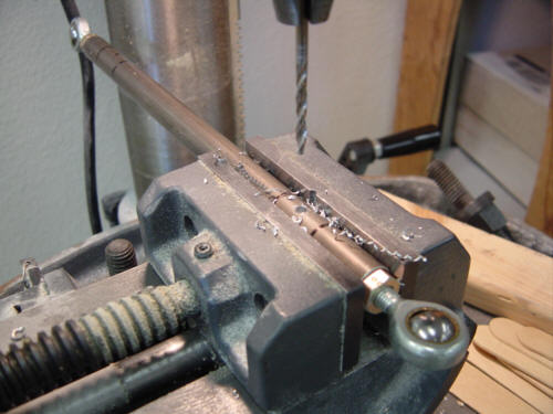
While that is curing, I worked on the ailerons themselves. The first thing to do is to cleanup the foam face and establish the correct angle for the forward face. This angle is the same as the Long-EZ and is taken from the pre-fab hinge re-enforcement plates from Brock. I used a angle finder to "score" the foam with the correct angle, then bar-sanded down until the marks no longer showed. Another change to the Berkut plans is the use of 7/16" thick steel rod instead of the original 3/8". This rod forms the counter-balance weight for the ailerons - larger ailerons require more weight. So, I ordered new steel rod and cut it to the exact length of the aileron. Because the rod becomes the actual lower leading edge of the aileron, it is necessary to remove some of the lower skin to make room for the rod. I started by removing some of the foam from the lower leading edge. Then, after factoring the amount of skin material needed to be removed to restore the original dimensions, I marked the cut line as Sandy helped hold the straight edge. After verifying the dimensions again, I slowly cut the excess material away slightly short, then used the 6-foot sanding bar to bring it to final dimension. Then, I took the aileron and tacked it to two parallel extrusions with a little superglue on the ends. The objective here is to get the bottom surface of the aileron in perfect alignment with the bottom of the rod - no lip, no goggle, and a smooth transition full span. This will directly affect the "feel" of the plane in a turn - the more true the alignment, the better the plane will "feel" on the stick. So, after verifying that the rod was de-gressed and clean, was perfectly straight, and the dimensions were correct - I clamped it to the extrusion and attached the rod with West flox. Let this cure, and let the jig do its job.
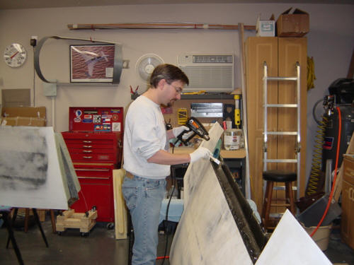
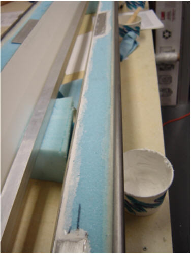
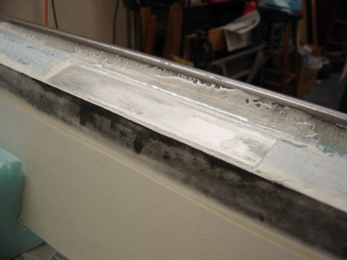
While waiting for the second aileron to cure, I trimmed the wing channels. It reminded me why I really hate working with carbon - that dust is ultra itchy!! I also opened up the wing root conduits in anticipation of installing the completed ailerons. Won't be long now....
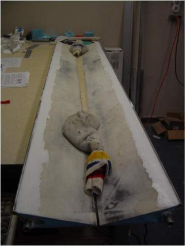
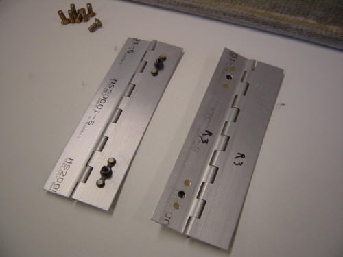
In preparation to attach the hinges, it was time to burry the reinforcement plates. With the foam already trimmed to shape, I marked where the hinges will go and cut some recesses in the foam for the A2 and A5 hinge plates. I also cut two 9" pieces of 3/4" diameter 2024-T3 .063 wall tubing for the imbedded torque tube. So, I had to mark and cutout the foam under the inboard plates. This tube will eventually be riveted to the inboard hinge, but in true Berkut overkill fashion - we add some golf-balling to give a little more bite to the slurry filler. When the tube is set in place, it will look something like this. A little sanding and cleaning later, these are now ready to bond in place.
More sanding...what a shock, I know. I took some 80-grit sandpaper to all the metal parts in prep for the bonding. Then, I outlined the plates on the foam and carved out a small slot along the upper skin of the aileron, mixed up some wet micro, filled up the slot and created a pad for the plate to bond to. When I pushed the plates into position, much of the micro oozed out - but that proved there was a complete bond. At the inboard section of the aileron, the torque tube is buried in medium-micro first, then covered with wet-micro and the inboard plate. In-between the hinges, I packed dry micro into the corner between the foam and the upper skin. After cure, this area will be radiused to facilitate a future BID cover.
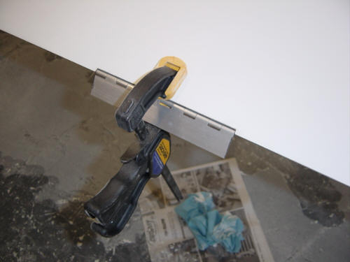
Now, before these hinge pads cure, it is important that the surfaces of the plates are parallel to each other - otherwise the hinges will bind when attached to the wing. To do this, the entire forward face of the aileron was covered with release material and an extrusion was laid on top of all three pads to keep them parallel. It worked, because when it was all cured and the peel-ply was removed, all the pads were perfectly straight! Success! Now, I get to do it all again for aileron #2...(sigh)
Well..#2 didn't turn out as good as the first. Actually, this aileron was the first one I cut from the wing and I had boogered up the foam a little experimenting with the correct cut angle - oops. This is no big deal in itself, but I had to fill the deviations with dry-micro and that is what caused the complication. The micro was rather stiff and when I put the outboard hinge pad in and it caused it to remain too far forward of the upper skin by a full 1/10th of an inch. That doesn't sound like much, but it would throw off the cosmetic looks of the aileron hinge line and could possibly induce some less-then-welcome "feel" to the stick. SOOOO...I performed surgery to correct the situation. First I VERY carefully cut the A5 plate out from the micro and foam, cleaned it off and got it ready to bond back in. You can see how deep into the foam I had to go to get it out, but this is all in front of the hinge line to it will only help to balance the aileron - that's a good thing. I whipped up a batch of less thick micro this time, and re-bonded the plate into place, placed an extrusion over all three pads and let it cure - this time with packing tape on it but without peel-ply so I could see what was going on. After cure, as you can see here, it was now exactly where it was supposed to be. Yeah! No harm, no foul...just a night wasted on repair. ...I'm sure it won't be the last - on to close out!
OK, now that all the hinge pads are in perfect alignment, it's time to bond on the front face of the aileron. After slurying the foam and filling in the rough spots in the hardened counter weight flox with new flox, I wet-out 1-ply of glass BID full length of the aileron lapping 1-inch onto the upper and lower skins - fully surrounding the counter weight rod. Then went back and wet-out another 1-ply BID layer but this time starting at the hinge line and only partly wrapping around the rod. Then I added peel-ply over the ends of the cloth to help smooth the transition onto the aileron skins. Once semi-cured, I sanded and applied dry micro to the lower leading edge to complete the smooth transition to the rod's leading edge. A little sanding and the little buggers are almost complete!
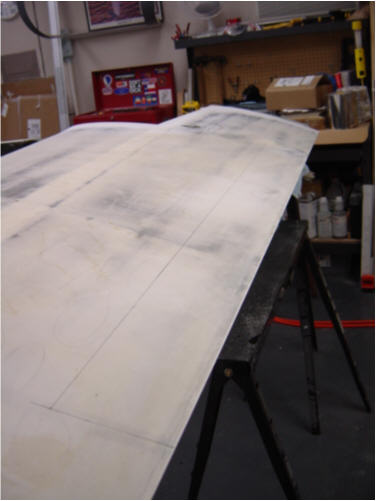
Unfortunately, I am going to have to halt aileron progress here for the time being. It seems that I have too much micro fill still left on my upper wing/aileron skins - about a .01" thickness. For proper alignment of the hinges and ultimately the ailerons, I will need to do more wing surfacing and remove that extra micro before going any further. So...back to sanding wings...even the one that I thought I had completed already. Oh well...more time, but hopefully well spent.
I have now completed the micro contour sanding and have covered both wing's top surfaces with UV primer. I'm ready to mount the ailerons, at long last! So, lets get started....
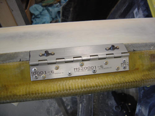
Now, you remember the hard points that were installed during the aileron assembly...well, now I have to attach the hinges to those hard points and to the wing. I started out by drawing the .02-inch deep hinge cut-outs on the wing. I took the air-saw and simply cut them out and beveled the forward edge of the well to match the curve of the hinge. Then I used some clamps and a straight-edge to align and super-glue attach the hinges to the wing well while making sure they are perfectly in line with each other. If they are not, the aileron will bind during its travel up and down - not good! With the hinges temporarily attached and aligned, I put the aileron back in the well to test for fit. Since I slightly changed the dimensions of the aileron's lower surface per Dave's amended instructions, I had to do some trimming on the lower surface edge as well. Once the well was had all the gaps set correctly, I clamped the hinges down and drilled out the mounting holes on all three hinges. Once drilled, I popped the hinges off the wing, cleaned them up with acetone, and installed nut-plates with flush rivets to the upper part of the hinges.
As a note here, the hinges are the same size and connected the same way as the Long-EZ - the only change is that more rivets are used for attachment and the outboard hinge is slightly further outboard. These changes were necessary do to the Berkut's larger and stiffer (carbon fiber) ailerons. The stiffness and increased aileron surface area both contribute to the Berkut's enhanced roll-rate as compared to the Long-EZ. Of course, the retractable gear and much reduced lower winglet also help out quite a bit. Ok, back to building...
Now comes the tricky part - aligning the hinges to the ailerons...with the correct alignment. First, I used 1/2" machine screws to attach the hinges to the wing. Then took more super-glue and put several large drops on the hinge side that faces the aileron. I replaced the aileron back into the well and used a couple clamps to hold it in the correct position. Then I slipped a small wire through the leading edge gap and lifted up the hinge so that super-glue bonds to the aileron face. I did this with all three hinges and let them dry for a few minutes. So, when I took the screws out and released the clamps, the hinges were now stuck to the aileron in perfect alignment for the next step. That process was much easier to type-up than it was in practice - very tedious to get it all lined up right without bumping anything out of alignment. I'm glad that's done.
To finish things off, I drilled 1/8" holes through the hinge and the hard point and used clecos to keep the hinge stabilized. Once the holes were all drilled, I popped the hinge back off cleaned it up again with acetone, debured the holes, sanded the hinge face and re-installed with wet-flox and self plugging rivets. A quick install back on the wing to check for proper travel and smoothness...and I'm happy to report I have BOTH!! Now...I get to do it all over again with the other one. Haha! as least I know what I'm doing this time - it went much faster this time around.
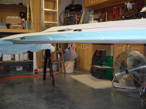
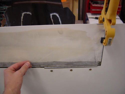
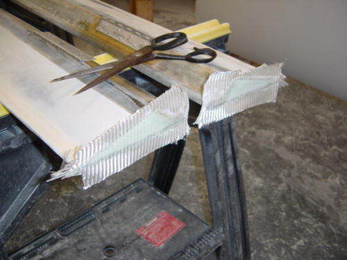
You will note in that last picture, the trailing edge of the aileron is raised a little when left hanging - this is very good and shows the aileron has the proper balance. You will also notice that the blue foam is exposed on the end - I'll fix that up right now. The two ends of the ailerons get 2-ply BID glass installed to close them out. These are very low-load areas, but to add some resistance to twisting.
First I removed 1/2" of foam from the inboard ends. The outboard ends are setup for very dry micro and flox corners for flat ends. After slurry is applied to the foam and flox is added to only the front tip the 2-ply BID glass covers are added to the inboard and outboard ends & let cure. To reduce the weight even further, I took some paper shop towels and blotted the end caps in conjunction with using a heat gun. I was able to get them pretty dry...kinda like a mini-vacuum bagging operation. After a little clean-up, they look great - inboard and outboard.
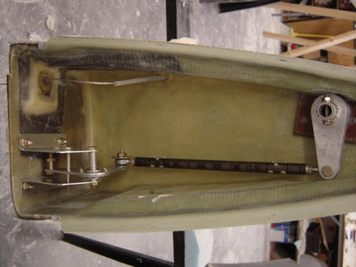
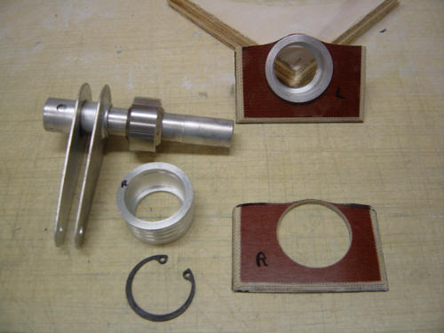
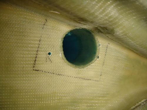
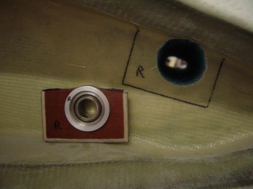
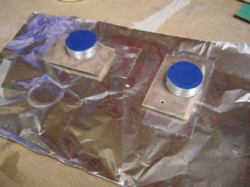
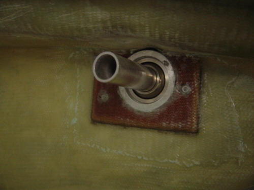
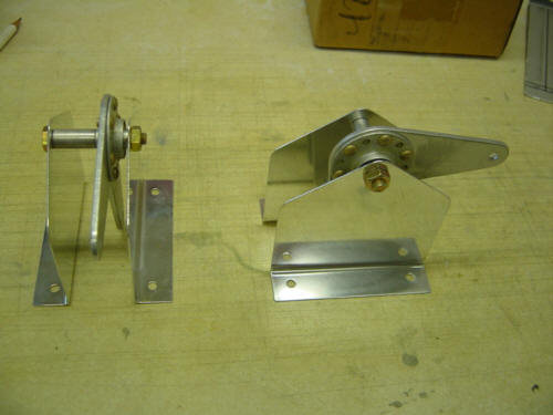
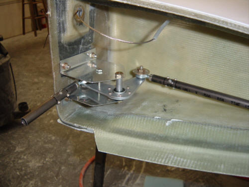
Well, now that they are mounted, it's time to make them do something...and do it in a controlled manner. The Berkut basically uses the standard Vari-Eze/Long-EZ aileron control linkage in the wing cavity, but with a few improvements. The first component, and improvement, is the inboard torque tube bearing and mount. For the prep-work, I made up a couple of 1/8" thick phenolic mounting plates, cut holes out for the receptacle, and made sure that all the part fit properly. I also installed a 2-ply BID the torque tube conduit in the wing root and made fine adjustments to the mounting plate assembly to get a perfect fit. I first flox bonded the bearing receptacles to phenolic plates, and taped the ends in prep for installing into the conduit with flox as well. The actual installation was a snap as I simply covered the back with flox, and squished it into position. I used a couple of pop-rivets to hold things in place and covered with a ply of BID for safe keeping.
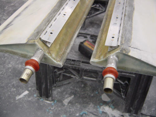
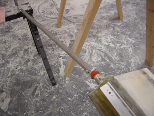
Now, the other end of that torque tube connects to the aileron. Actually, it attaches to universal joints that are attached to the aileron stub. Once in place, it looks something like this. The rest of the "magic" exists in the bell cranks and push-rods that will be installed into the wing root. These are the same standard steel structures that the Long-EZ uses. However, the push-rod is made from Titanium tubing and is both fire resistant AND lite - a perfect combination! After spending several hours getting all the dimensional relationships in check...I finally got all the hardware mounted. I also added the receiving end of the push-rod quick-connect that will run between the control sticks and the wing.
Ta-da!! The ailerons are done! A little more sanding and filling and they are ready to fly! Check the Control System section for more on hooking the ailerons up to the cockpit sticks.
 Back to the Proto-page