There have been several improvements to the Berkut design since I started building. One of those is the use of the rear fuel compartment in the strakes as the fuel sump and the addition of fuel transfer tubes and check valves. These transfer tubes allow fuel to flow (one way) from the forward fuel compartments, to the rear compartment where the main pickup tubes are located. This method does away with the large fuel sump in the passenger's seat.
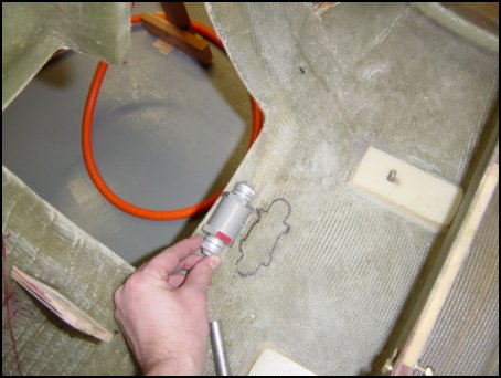
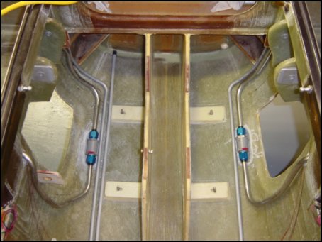
I first started by choosing the placement of the one-way check valve. The reason I traced it on the floor will become obvious shortly. The next few steps were VERY difficult. 1/2-inch stainless steal tubing is formed to route fuel from the aft-most corner of the front fuel compartment to the check valve. This may LOOK like a simple task but if you ever try to cut or bend this type of tubing...well...just avoid having to do it, it's terrible to work with! But as you can see, I finally wrangled all the transfer lines into place and it only took about 3 hours. Note: the aft-most tube is 3/8-inch aluminum and serves as the pickup line that leads to the fuel valve in the front of the plane. By the way, the reason for the stainless tube is that should the main gear ever depart the aircraft (God forbid!), this will assure that fuel lines are not easily punctured and greatly reduce the risk of post-crash fire.
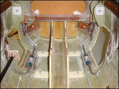
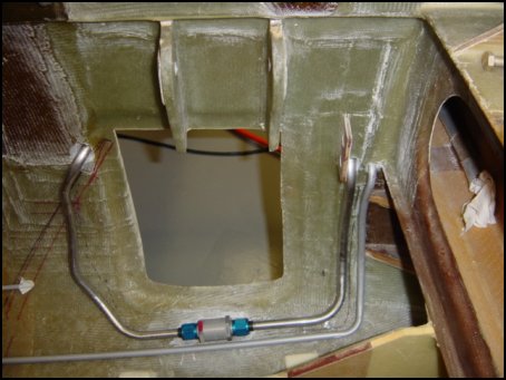
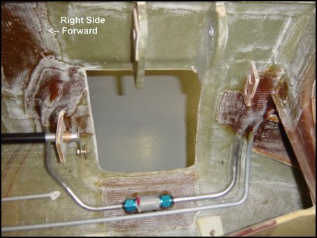
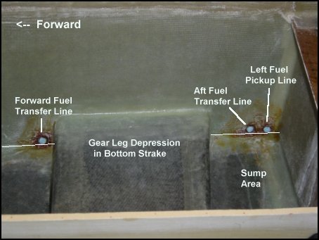
Back at the ranch, I'm still at work bending tubing to complex curves but I finally get all of the settled into a trial fit. Next, I dug out and glassed in a small depression in the floor of the fuselage so the top of the valve will clear the gear leg when extended. Once that all cures, it's time to bond it all into place with liberal use of wet flox in the holes and drier flow under and around the tubes all with 3-ply BID on top. Here is what the finished product looks like: Right side fuel transfer valve Here is a picture of the inside of the strake showing the left side fuel transfer and pickup tube locations.
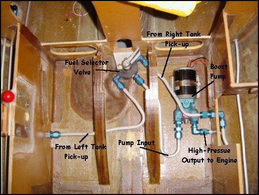
In the front seat area, the fuel boost pump and selector valve are installed. The right and left tanks have independent pickups and are both routed to the fuel selector valve located between the pilot's legs for easy access. The selections are (counter clockwise): Off, Left Tank, Right Tank, and Off. The fuel from the selected tank then flows to the electric boost pump and then to the engine. Just behind the front seat bulkhead is the fuel filter. I located it in the aft compartment mainly to it is easy to service. This is as far as I can really go until the engine is installed so I know exactly where to punch through the firewall. I'll also install a fuel flow sensor, but don't which one yet as it depends on the engine monitor I'm going to install.
More to come as I work on completing the fuel system after I get the engine installed.
NOTE: Obsolete section below. Although I have completed the aft fuel sump long ago, I am not going to install it in my Berkut. There have been several advancements in the last several years, and one of them is the addition of internal strake sumps and transfer system. This is a very simple system and I have decided to install it instead, and with it a few of my worries go away too. The original sump design is perfectly safe and sound, but not having my passenger sit on two gallons of fuel is just a little reassuring. Plus, I'll use that extra room for map/accessory storage or maybe a CD changer.

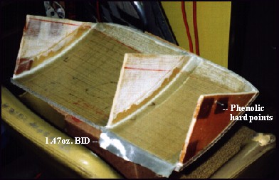
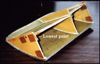
The fuel sump is actually the rear seat thigh support. It will contain seperate compartments, drains and pick-ups for each fuel tank (Left and Right). The fuel valve at the front of the pilot's seat can select which tank feeds the engine (L, R or Off). The thigh support, which comes pre-molded from EAI, is first contured to the bottom of the fuselage. Then phenolic hardpoints are added to the side bulkheads. There will a hardpoint for the main pickup, fuel sump (bottom) drain, vent, aux. fuel feeder for each compartment. The sides are bonded to the thigh support with 2-ply BID and 1.47oz BID cloth is added as an additional sealant (don't want ANY leaks on this thing!). The bottom blukhead stock is trimmed such that the lowest point is the corner where the fuel pick/sump drain are located. The bottoms are bonded in place with 2-ply BID.
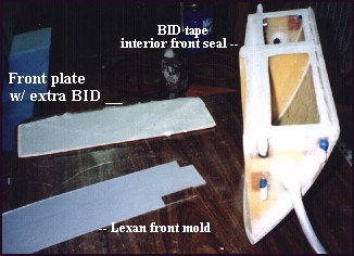
Once the main structure is complete, large holes are cut in each side and 5/8" versi-tube is floxed into place and re-enforced with 3-plys of BID on each side. These tubes will serve as the main fuel feeder from each tank. Holes are drilled and tapped into the phenolic hardpoints and AN fittings and drains are bonded into position. At this point a flop tube can be installed in the large compartment. I elected not to install one - I don't plan to fly upside down for entended periods and the Prototype #0001 had a inoperative tube for years and never skipped a beat. Next, a Lexan sheet is used to place a 2-ply BID tape around the inside front face of the sump. This provides a seal and bonding surface for the front plate.
Finally, the front face is bonded into position with an additional ply of BID for additional seal strength. Once everything cures, the AN fittings are plugged and a vacuum is applied to the sump. It is measured by a sensitive vacuum guage or an altimeter. If the sump holds negative pressure for at least one hour...the tank is sealed. If not, you have to find and plug the leak. My sump did not leak...Success!
 Back to the Proto-page