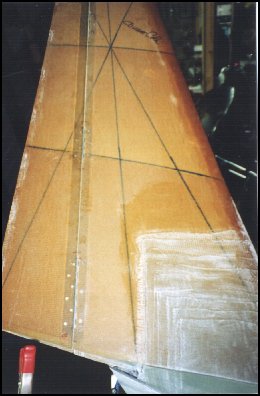
Now that the winglets are mounted on the wings, it's time to cut out and install the rudders. First, the rudder dimensions are verified and an aluminum straight-edge is used to align the cut line. It is clamped to each end of the winglet and super-glue is used to tack the middle section and keep it from sagging. Carefully using a reciprocating air saw, I cut through only the layers of glass on each side of the winglet. Once the cutting was complete, a razor was used to cut the remaining foam and sever the rudder cut-out from the winglet. The two rudder cut-outs were then trimmed up and a channel in the foam was created to accommodate the hinges that will be added later. A similar process is performed on the winglet side of the rudder. I used a small Dremel tool and a tongue depressor with 36-grit sand-paper on it. This method worked well, but I'm sure that a better method exists out there somewhere.
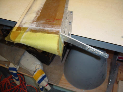
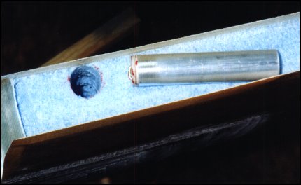
A short piece of 1 1/8" OD aluminum tubing is used for a rudder return spring housing. A piece of ply wood was cut and super-glued to the tube. The entire assembly is bonded into the foam with a slurry of micro and epoxy. This plug end holds a hook made of hinge rod. The hook will be used to attach the winglet side of the return spring to the rudder. Without this little gizmo, the rudder would flop around and that never did a plane any good! Two plys of Bid are added over the entire channel with additional plys added under the hinge mounting positions.
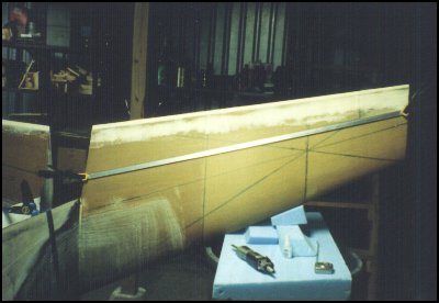
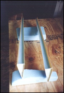
Aluminum hinges are added in three positions and bonded to the rudder with epoxy and rivets, and attached to the winglet with machine screws and nut-plates. This allows the rudder to be removed in the future for inspection or repair. This picture of the two winglets with rudders installed shows the channels, hinges, mounting plates and the difference between the extended and retracted rudder.
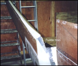
Once the rudders are mounted on the winglet, the rudder control horn is bonded and riveted to the lower end of the rudder. The rudder control horn is basically a lever connected to the rudder cable and gives the rudder a major mechanical advantage! A secondary advantage is the reduction of drag because all the components are internal to the winglet - unlike the original Long-EZ design.
One word of advice, stay off the rudder peddles if you want to fly straight! :-)
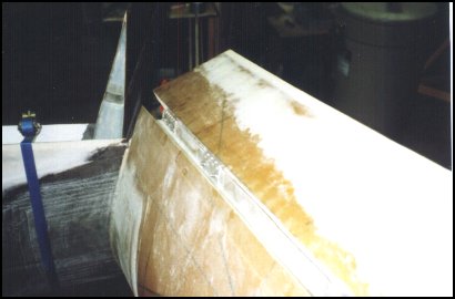
Well, here is an other little victory...and completed part. The picture above shows the final two lay-ups on the rudders. Now that the wing tips and the lower rudder fairings are complete, the rudder is cut away from the winglet fairing so the final closeouts can be completed. The lower aft tip is filled with flox and covered with 2-ply of BID for 'bump' resistance. The forward section is closed with 1-ply BID and flox corners. These are mostly cosmetic in nature, but otherwise you would be left with raw foam.
This section is now complete...it took a decade...but complete it is!
 Back to the Proto-page