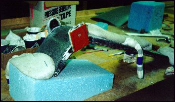
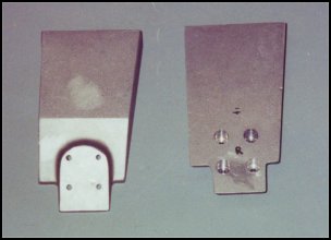
The gear design was developed by Shirl Dickey (inventor of the E-Racer) and further modified and strengthened by Dave into what you see here. Above is a picture of the tabs that connect to the retract arms and pull the gear up into the retracted position. I have added phenolic plates and flox on both sides of each of the tabs. This added about 3/4" thickness to the tabs. The hole is then drilled out to a larger dimension and chromemoly bushings were floxed into place. Not shown in this picture is the center pivot bushing that is floxed into position and covered with 8 plys of carbon tape. The strength of this totally carbon strut is amazing...and what's even more amazing...is the amount flex achieved at the lower 1/3rd of the strut. They look very stiff...but the design does allow for plenty of flex.
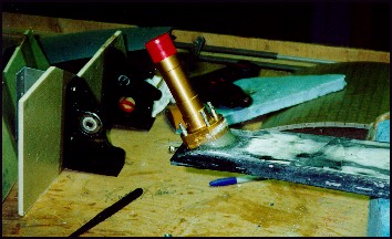
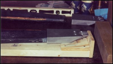
On the other end of this carbon monster is the wheel axel. In this picture, the axel is held in position with AN bolts that are recessed into a chromemoly steel plate on the back side of the strut. Flox is used to make a pad under the axel and adds significant strength. Also seen in the background are the MG-30 stringers. These are the structures that the gear legs will attach to.

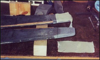
It's been awhile since I've updated this section. The Berkut folks have had some time to improve on the design. As you saw in the section above, the gear legs simply had a steel plates behind the gear leg attached to the axels. Well, now they have taken it to an extreme. Manditory for the 540 equipped Berkut, I'm adding the Talons to the existing gear legs to increase strength, heat resistance and allow easy replacement. Although it is not mantitory for a 360 equipped Berkut, the benefits outweigh the extra time and effort.
The first step in retrofitting the gear is to remove the steel plate and cut off the ends of the gear legs. (yeah, it was hard to bring myself to do it) After the ends are cut off, the legs are sanded and shaped to fit inside the cast aluminum 'Talons'. Of course, a ply of BID has to be added between the carbon strut and the aluminum - as an electroletic reaction will occur unless insulated resulting in heavy duty corrosion. After a good fit is created, a jig is created to hold the gear leg and Talon in the correct position both in length and in twist. The inside of the Talon is sanded and prep'ed for attachment. The jig is mounted vertically and secured holding the gear leg in position. Duct tape is used to make a funnel so that the wet flox is captured and pooled as it is squeezed out of the Talon. This will allow any bubbles to float to the top and be easially removed once cured. Once cured, the new Talon is cleaned of excess resin and ready to be re-installed on the plane. How Kewl is that!?!
 Back to the Proto-page